| Page Created |
| June 1st, 2024 |
| Last Updated |
| October 27th, 2024 |
| Great Britain |
 |
| Related Pages |
| British Aircraft |
| Crew |
| 2 |
| Length |
| 20.40 metres |
| Wide |
| 26.80 metres |
| Height |
| 5.90 metres |
| Weight |
| 3,855 kilograms |
| Loaded Weight |
| 6,900 kilograms |
| Propulsion |
| – |
| Armour |
| – |
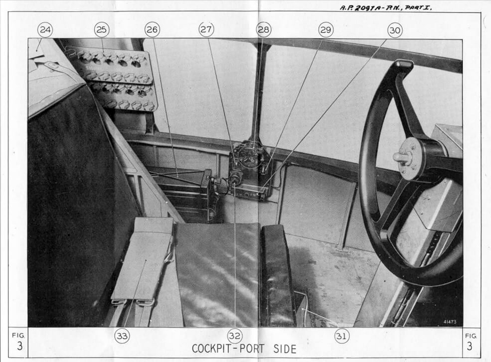
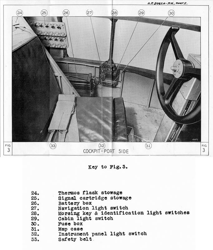
| Armament |
| – |
| History |
The glider, demonstrated by the Luftwaffe at the Belgian fort of Eben Emael in 1940, has a significant attraction: like modern troop-lift helicopters, it can land a formed group, usually a platoon, on a compact landing zone. The British require their glider pilots not only to deliver men and equipment safely into battle but also to join the fight as infantry after landing. Paratroops, while less vulnerable, can be scattered by wind or the speed of their exit from the aircraft, delaying their formation into an effective fighting force.
In June 1940, the British airborne force is established following Prime Minister Winston Churchill’s directive, in response to the German use of airborne tactics during the Battle of France. As airborne forces are being developed, the War Office decides that gliders will play a crucial role in this new capability, aimed at transporting troops as well as heavier equipment, which by 1941 includes artillery and tanks.
By early 1941, the War Office issues four specifications for military gliders. The first, Air Ministry specification X.10/40, is for an eight-seat glider, modelled after the German DFS 230, which becomes the General Aircraft Hotspur I. The second specification, X.25/40, leads to the development of the Slingsby Hengist, which can carry fifteen troops. The third specification, X.26/40, results in the 25-seat Airspeed Horsa. Lastly, specification X.27/40 calls for a glider capable of transporting heavy loads, including light tanks.
The British aeronautical industry, already strained by existing production demands, has limited capacity for the design and manufacture of gliders. As a result, the government allocates contracts to appropriate firms rather than through competitive tender. Slingsby is tasked with developing X.25/40 due to its limited size and production capabilities, while Airspeed is assigned to build X.26/40. General Aircraft Limited, having already produced the Hotspur glider, is selected to develop X.27/40, as it is considered capable of producing a larger glider.
Airspeed Limited receives this specification and begins producing initial designs at Hatfield under the leadership of A. Hessell-Tiltman. With the war effort in full swing, the parent company, de Havilland Aircraft Company, which has recently acquired a controlling interest in Airspeed, provides support. However, the team works in the classrooms of the de Havilland Technical School, which is not ideal due to the constant threat of air raids. Consequently, the Airspeed team relocates to Salisbury Hall in nearby London Colney. Salisbury Hall also houses the DH98 Mosquito design team, led by Ralph Hare and Ron Bishop. The Mosquito, later dubbed ‘The Wooden Wonder,’ benefits from the synergy between the two projects.
The final design for the new glider is completed in just 11 months, an extraordinary achievement given that Britain is at the height of its conflict with Germany and the Battle of Britain is being fought in the skies of southern England. Airspeed’s Horsa design is accepted, and an initial order for 400 units is placed in February 1941.
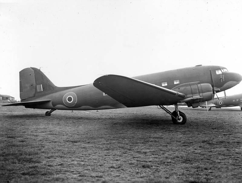
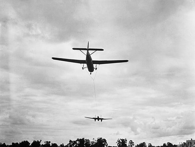
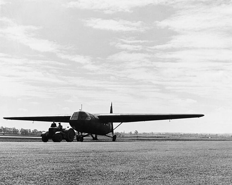
With the designs complete, the first two prototypes are built at Salisbury Hall before being transported to the Fairey Aviation Works at Hayes, near the Great West Aerodrome. The first prototype, DG597, is first flown on September 12th, 1940, by George Errington. It is towed into the skies over West London and Berkshire by an Armstrong Whitworth Whitley, then released and landed with very little difficulty. Allocated the Airspeed designation AS.51, the type is christened Horsa, after the legendary fifth-century conqueror of southern Britain. Five additional prototypes are quickly assembled and test flown at the Airspeed Works in Christchurch, Dorset.
Airspeed’s production order for the Horsa glider is increased, with the first production model rolling out in June 1942.
Discussions take place regarding the possibility of producing an additional 400 gliders in India. However, on April 1st, 1942, the Indian Defence Department reports to the War Office in London that there is no suitable indigenous timber available in India, and importing the necessary materials would make production prohibitively expensive. As a result, the idea is abandoned.
If it had been feasible to produce the Indian Horsas, they would have been deployed to the Middle East, as it is decided at that time to limit airborne forces in India to paratroopers only. Moreover, there are unlikely to be any glider pilots or tow aircraft available in the region for the foreseeable future. Nonetheless, another report from India, sent in April by General Wavell, Commander-in-Chief, reaches the War Office. Wavell informs them that operations are being planned in Burma for the autumn and inquires about the possibility of obtaining 200 American Waco gliders.
This leads to a coded message from the Ministry of Aircraft Production in London to the British Air Commission in Washington on August 31st, 1942, stating: “Scheme to produce Horsas in India abandoned. Requirement: 20 Wacos and ten glider pilots to arrive in India by early 1943 to facilitate planning of a glider-borne force. An additional 200 Wacos to be delivered by June 1943.” It is now decided that gliders are necessary to carry supporting arms for the paratroopers, and by mid-1944, 500 Wacos, along with American glider pilots, have been delivered to the Far East.
As soon as production begins, expert subcontractors, some with decades of experience in wooden furniture, suggest a number of improvements and refinements. These enhancements result in the AS.58 Airspeed Horsa II.
This modified design features a reinforced floor and a hinged nose section to accommodate military vehicles for both transport and combat roles. Another significant upgrade includes the installation of a stronger twin nose-wheel and a modified tow attachment. These modifications increase the all-up weight to 7,140 kilograms. It is worth noting that although Airspeed Limited is responsible for most aspects of the Horsa II, they never manufacture or assemble any of this model.
| Design and Features of the Horsa Glider |
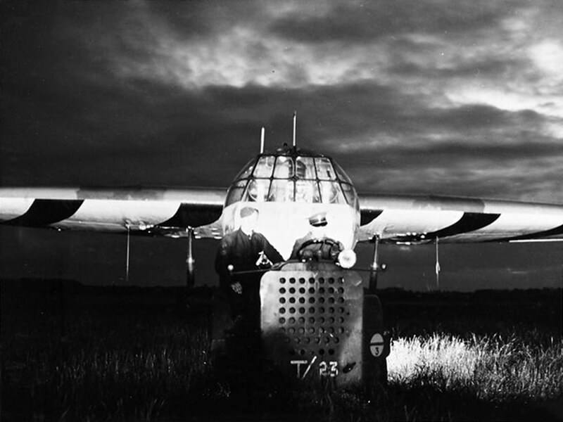
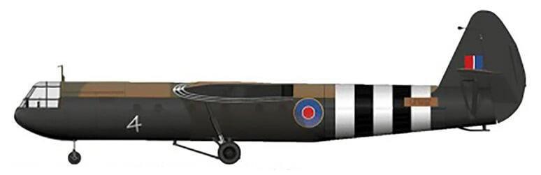
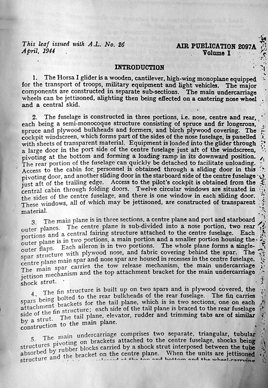
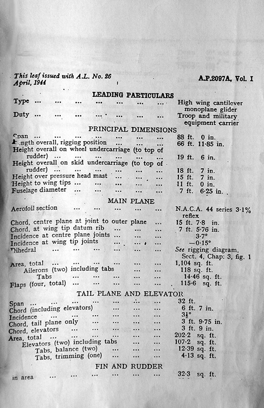
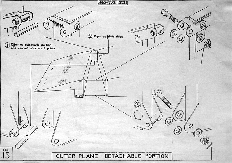
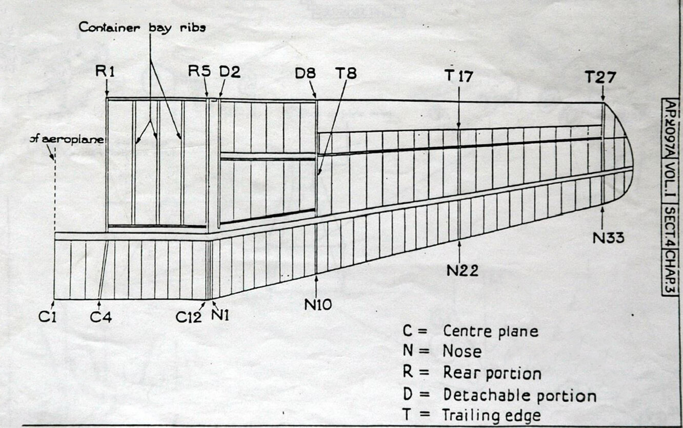
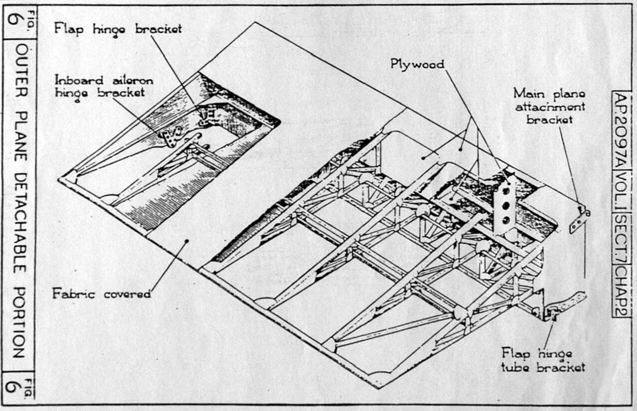
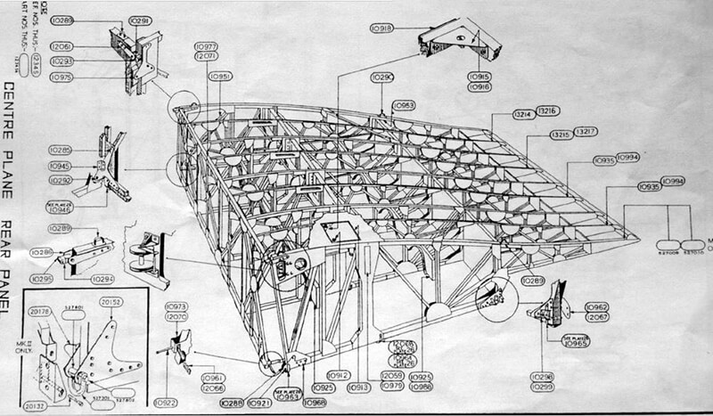
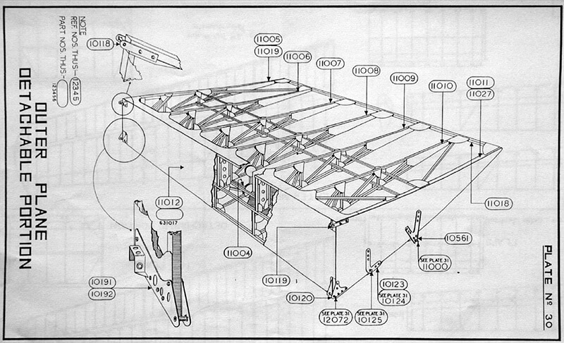
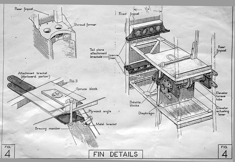
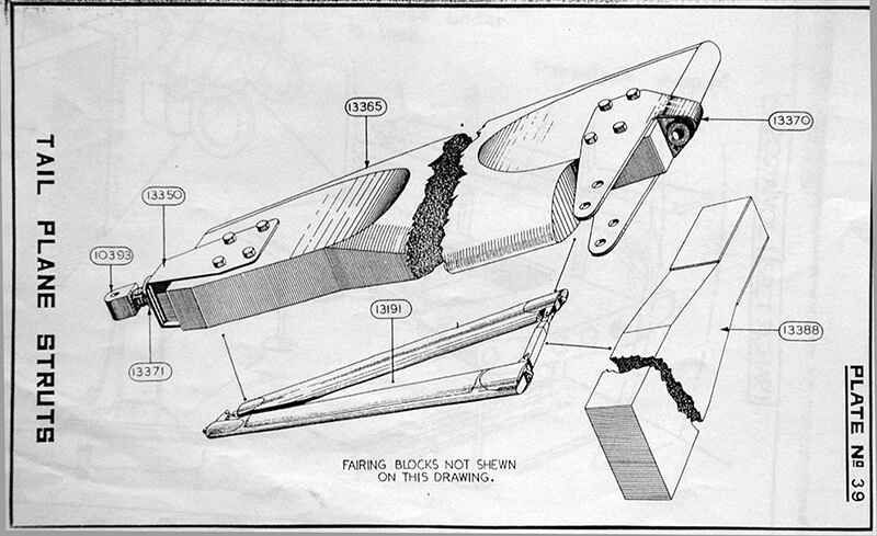
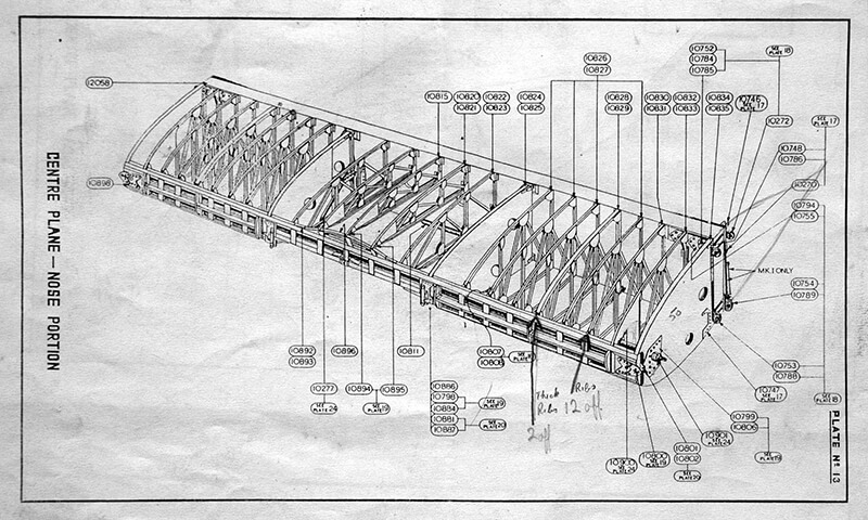
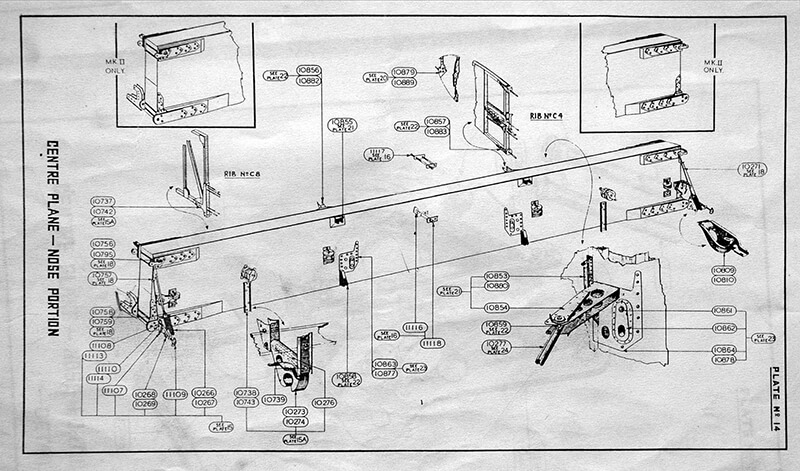
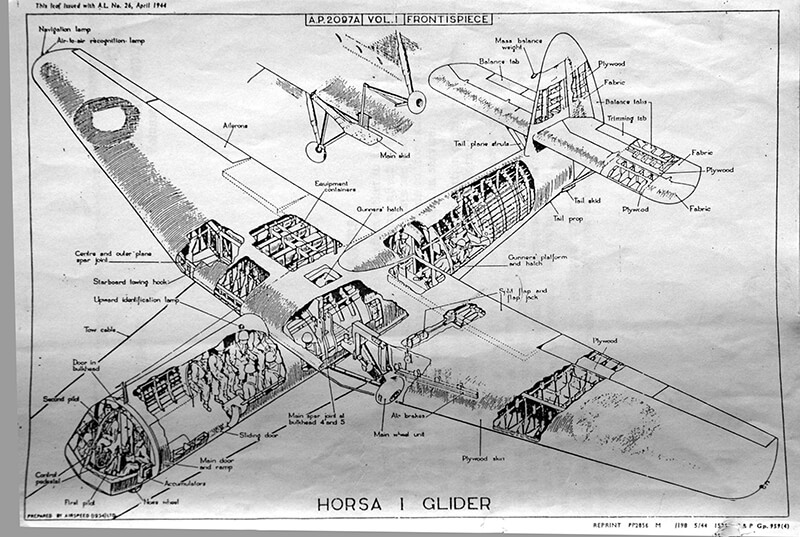
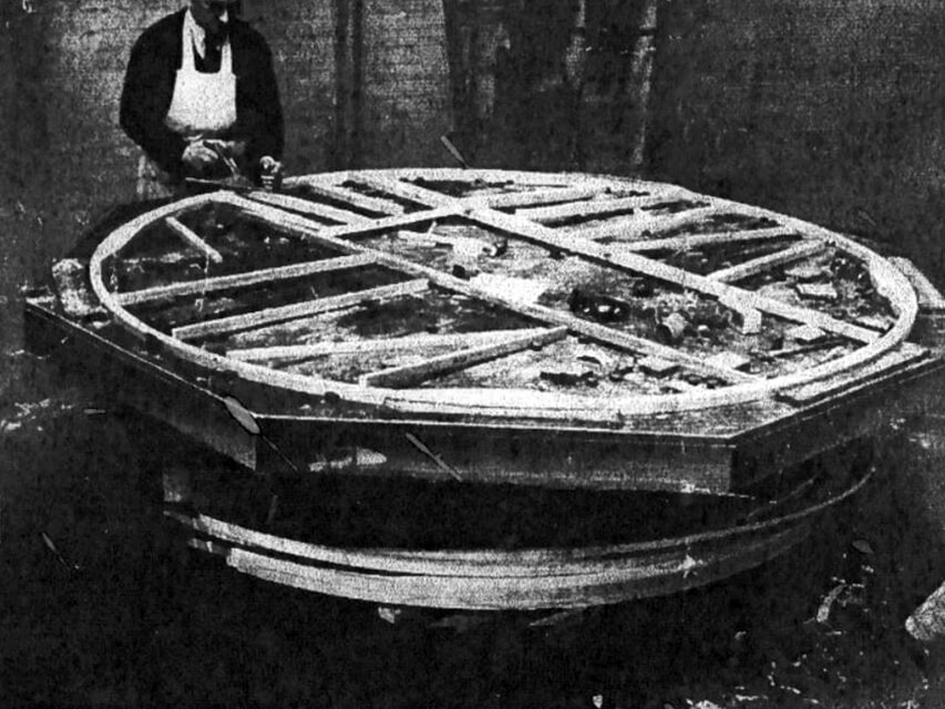
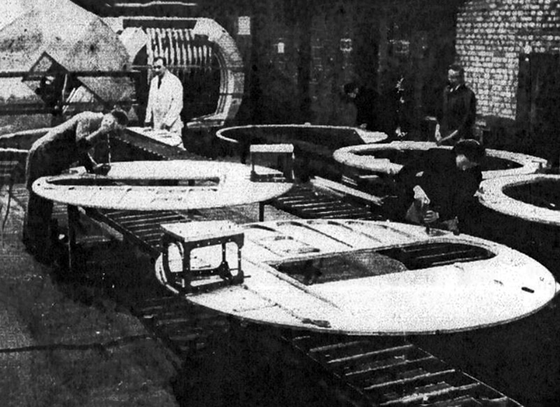
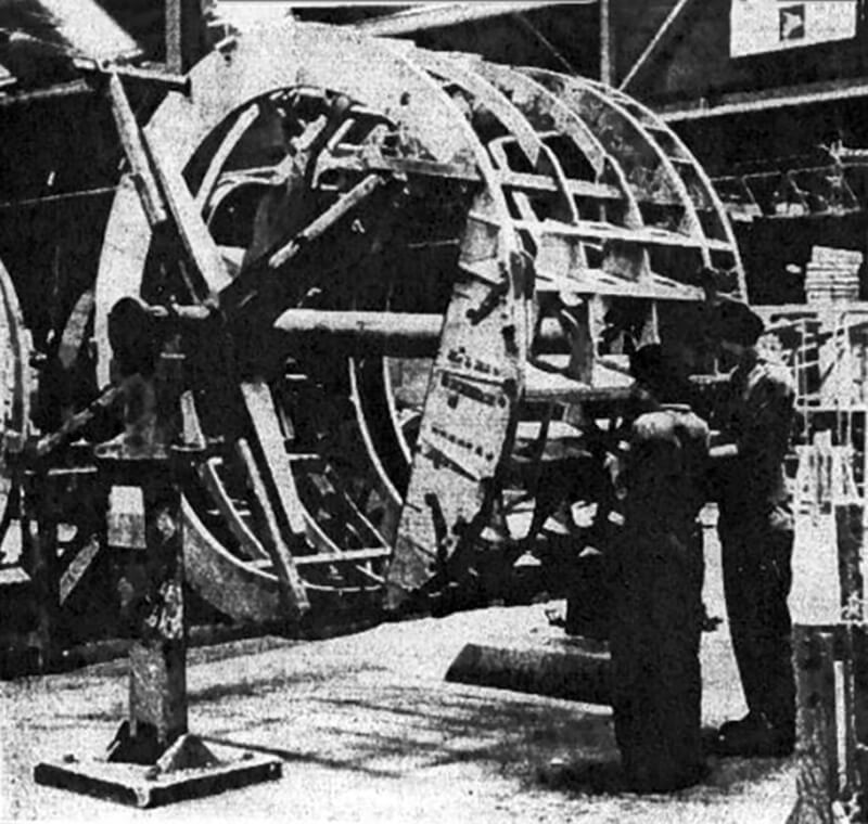
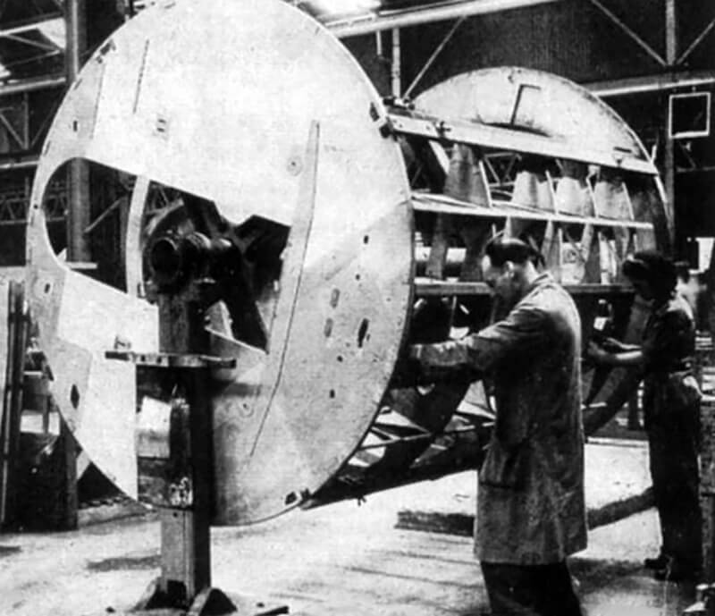
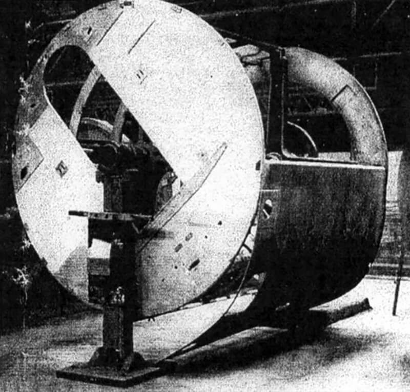
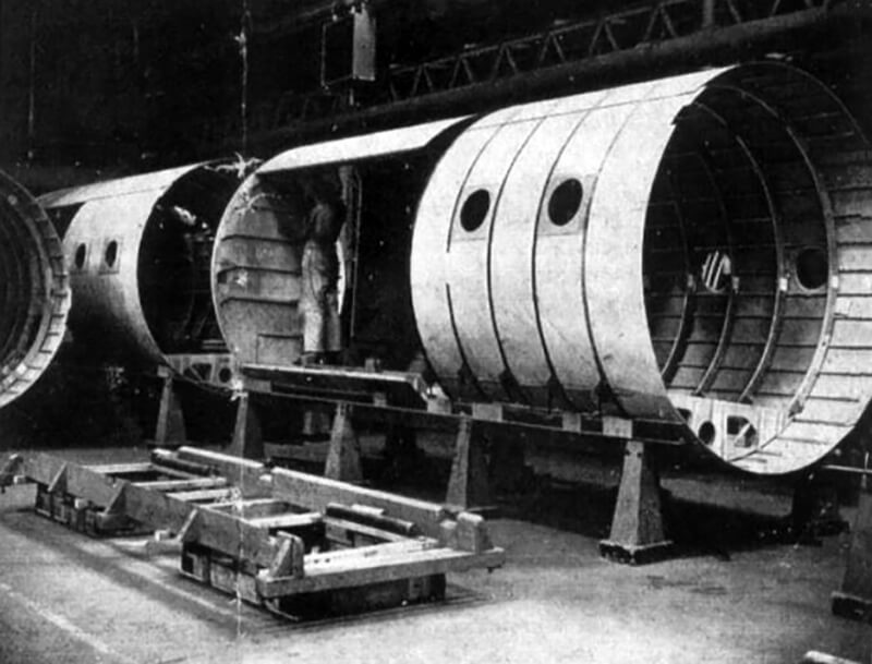
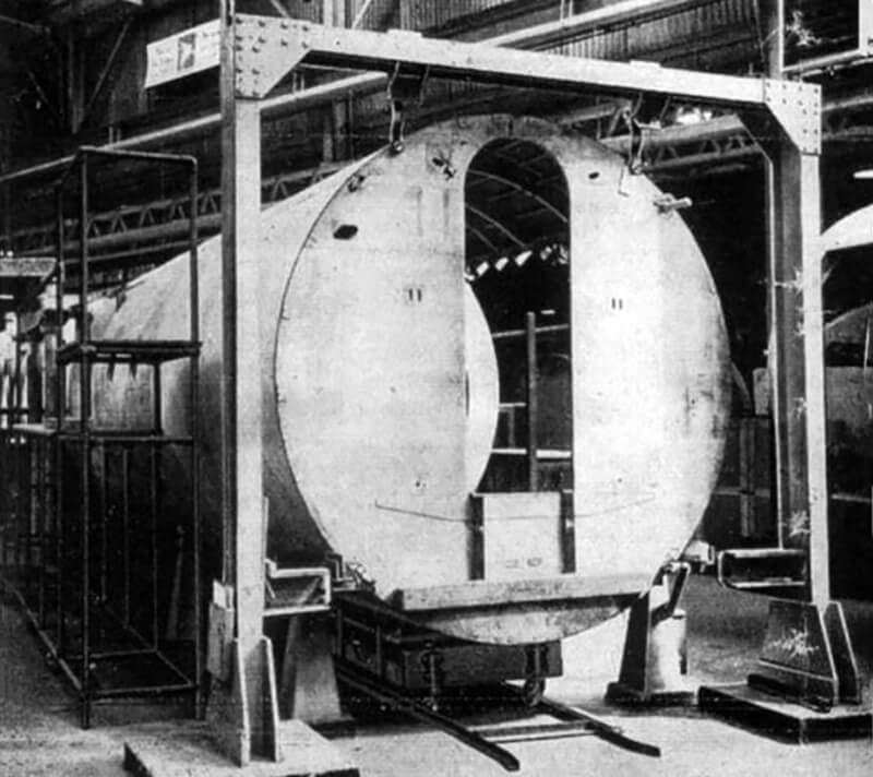
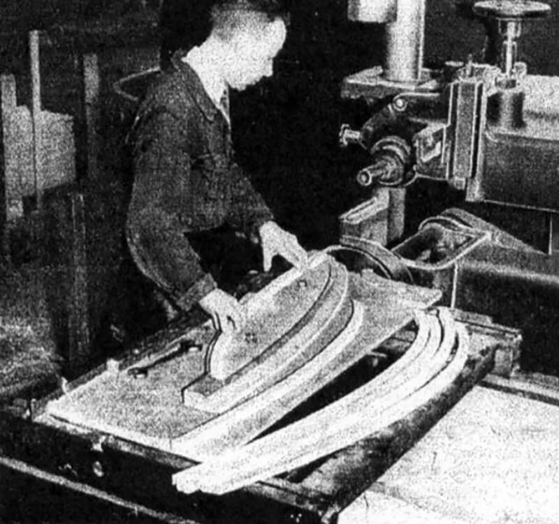
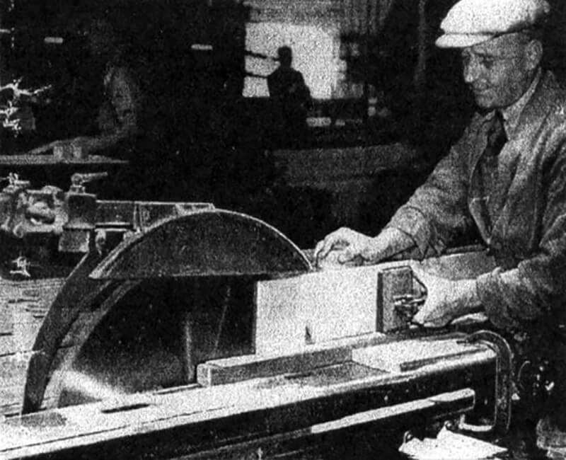
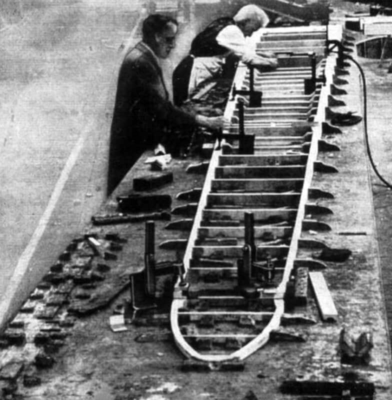
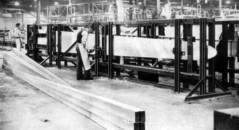
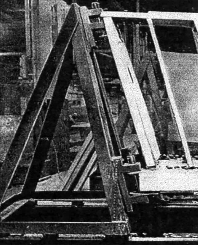
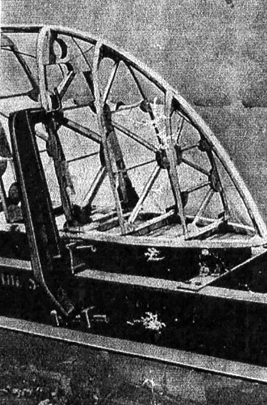
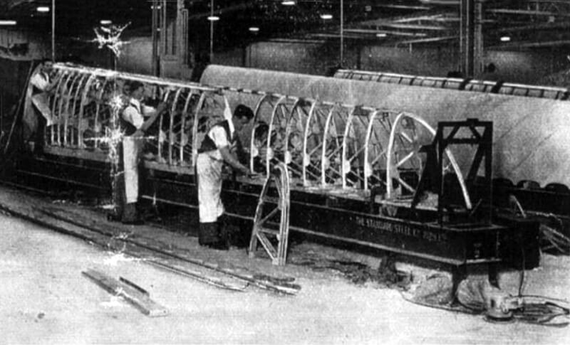
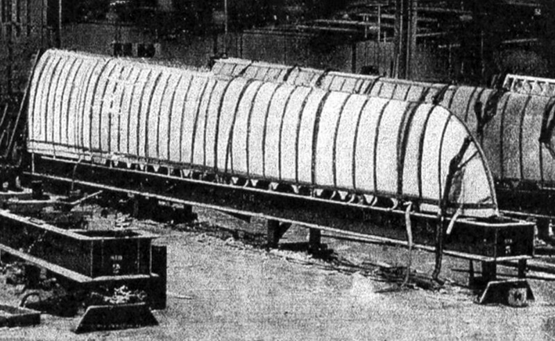
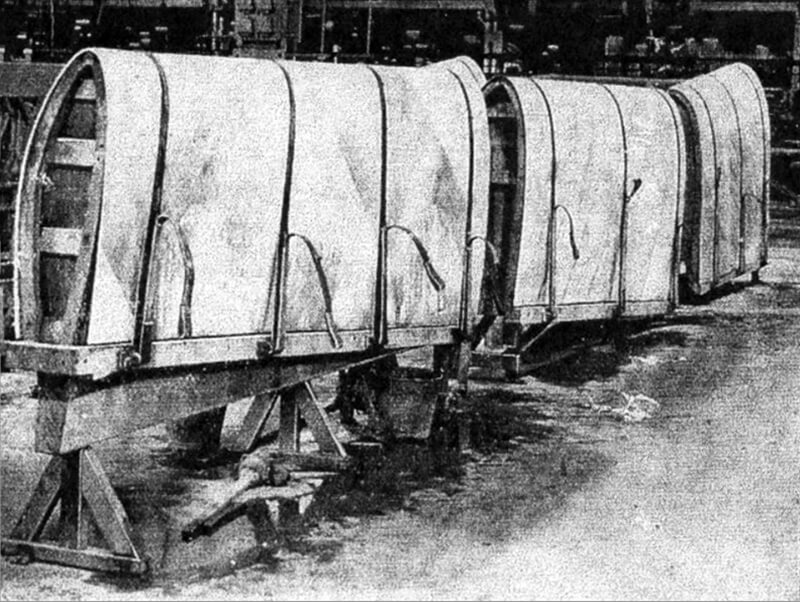
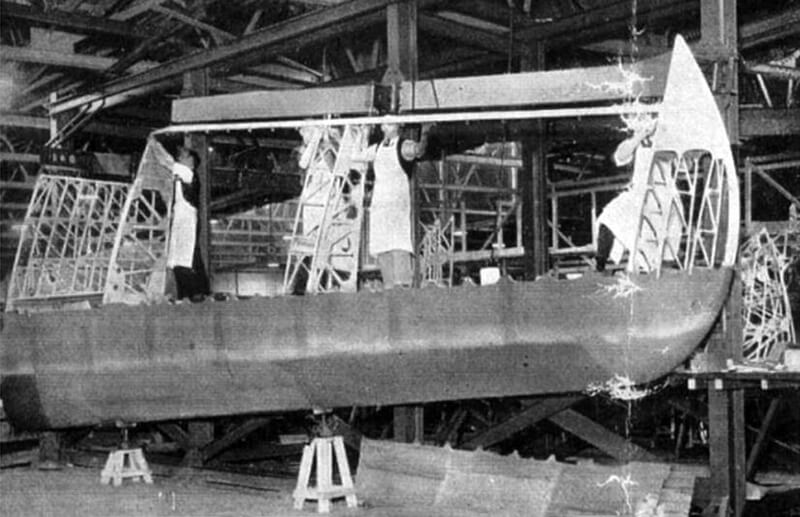
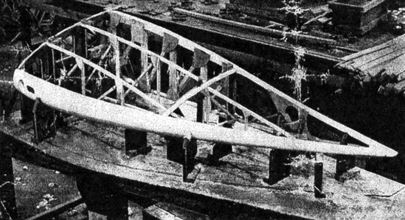
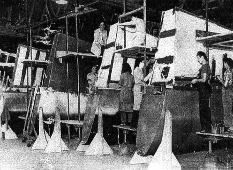
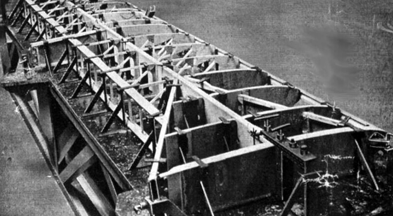
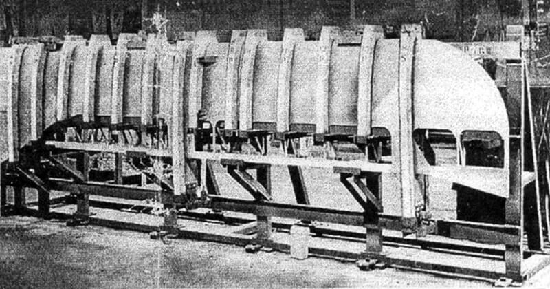
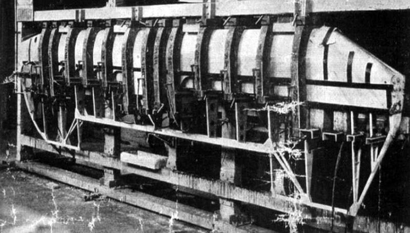
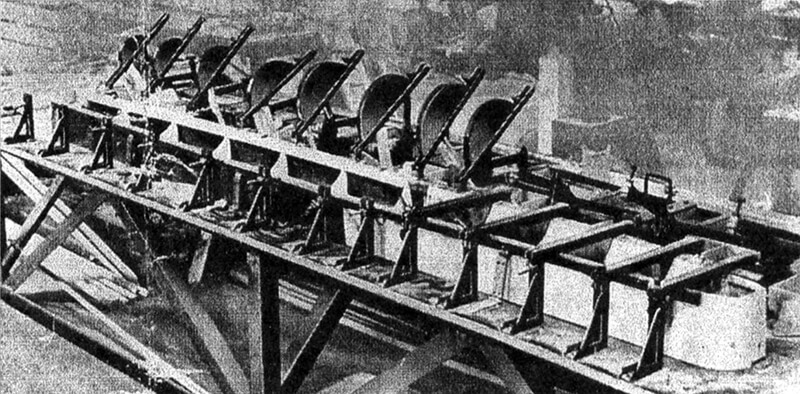
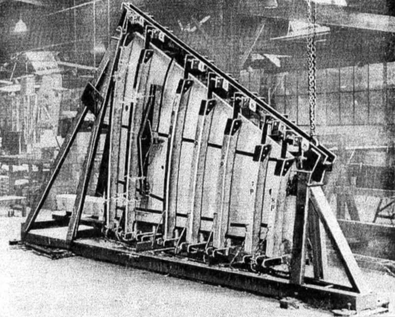
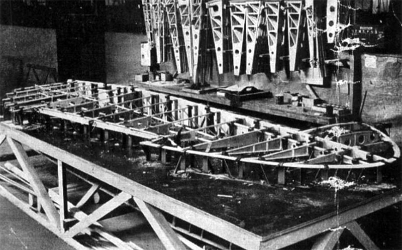
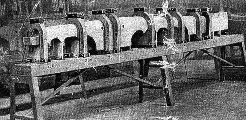
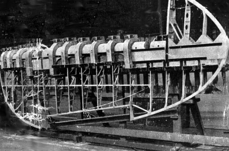
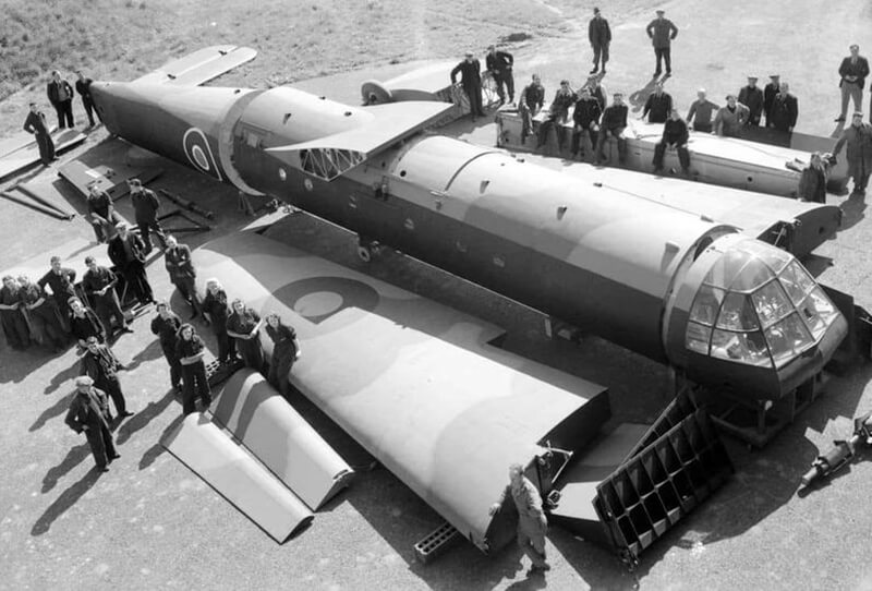
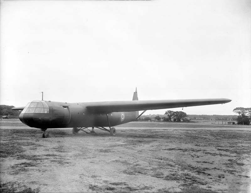
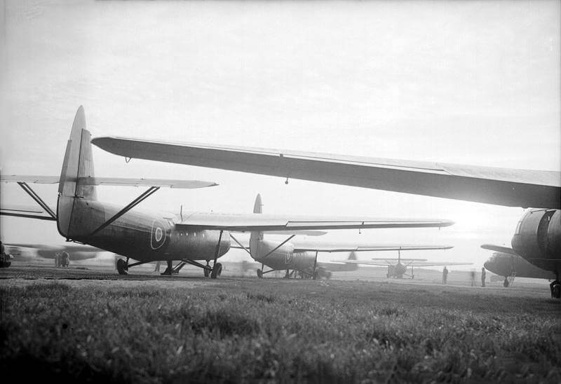
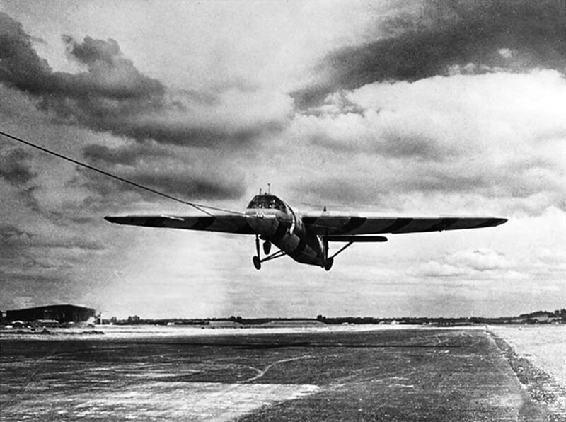
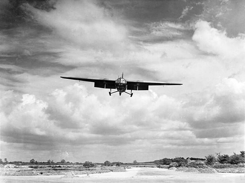
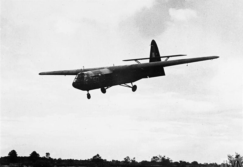
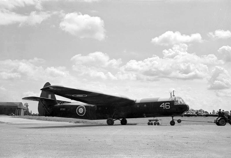
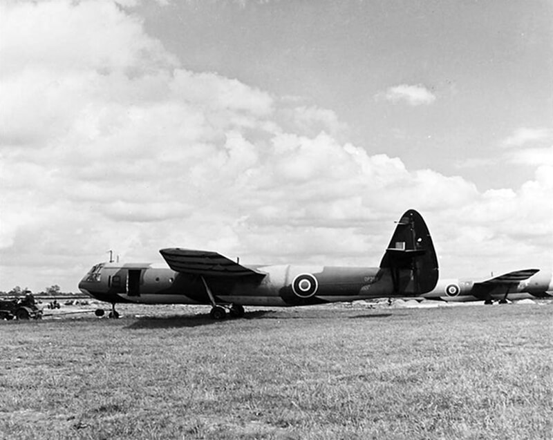
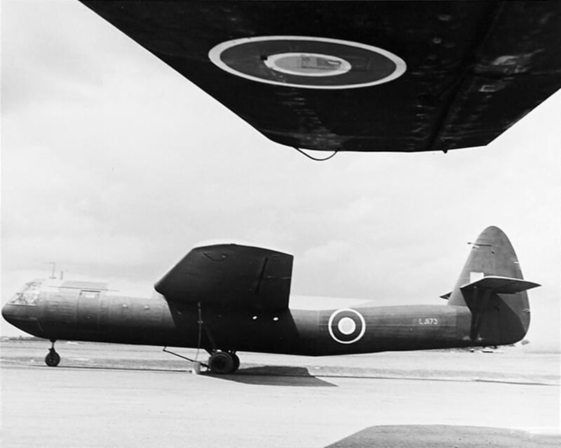
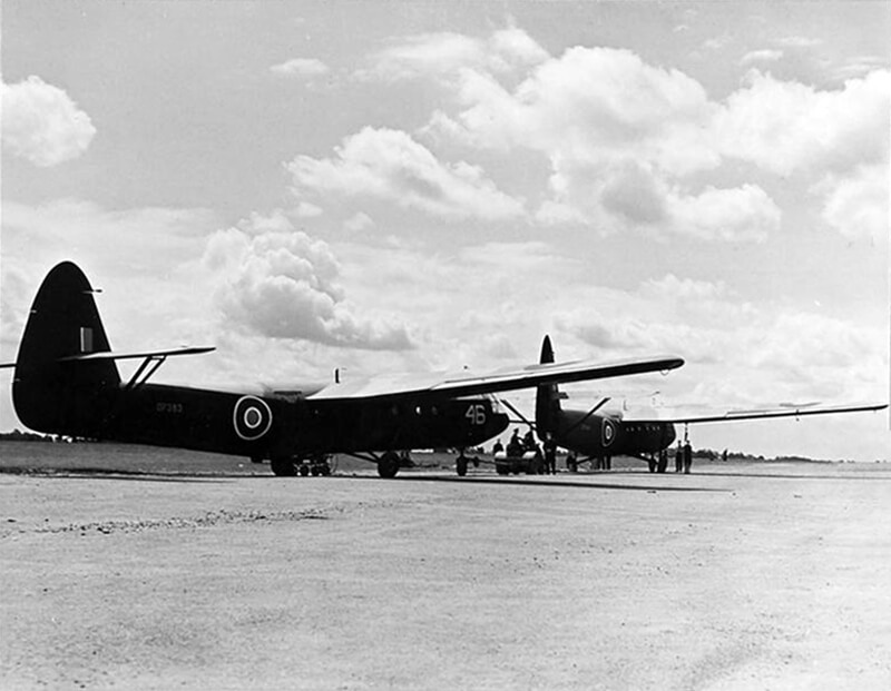
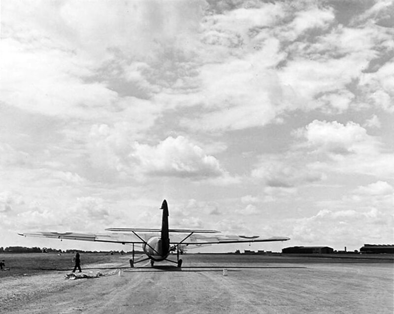
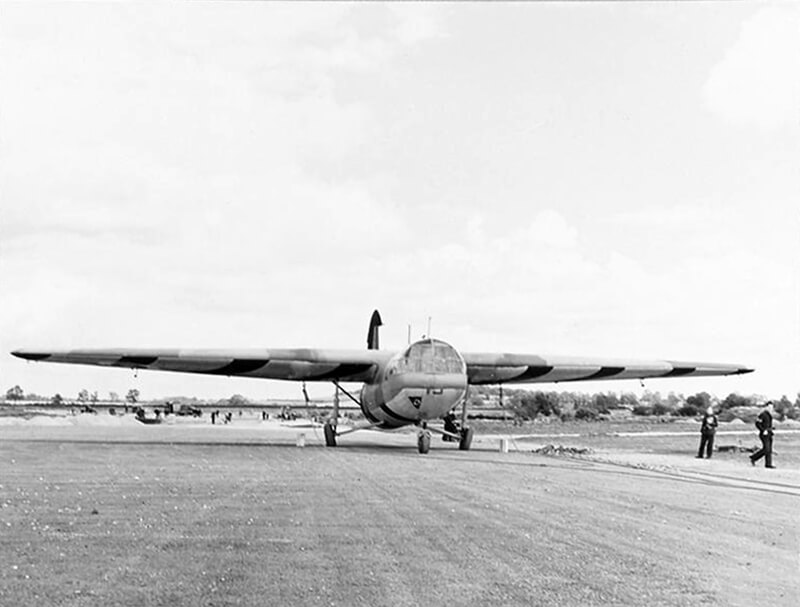
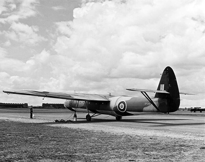
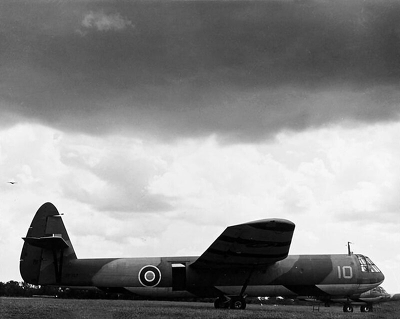
The Horsa is a high-wing cantilever monoplane with wooden wings and a wooden semi-monocoque fuselage. The fuselage consists of three bolted sections: the pilot’s compartment and main freight-loading door at the front, accommodation for troops or freight in the centre, and the tail unit at the rear. Airspeed subcontracts construction to Austin Motors, and furniture manufacturers like Harris Lebus also contribute, given the significant use of wood in the airframe.
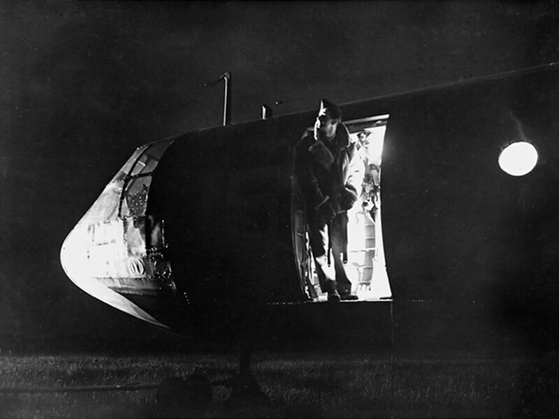
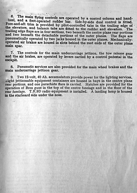
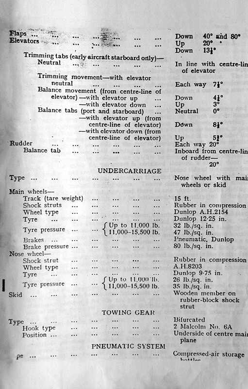
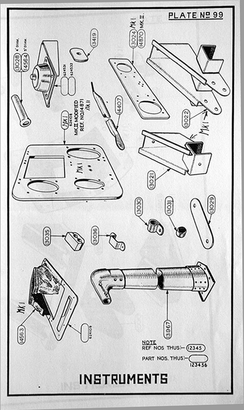
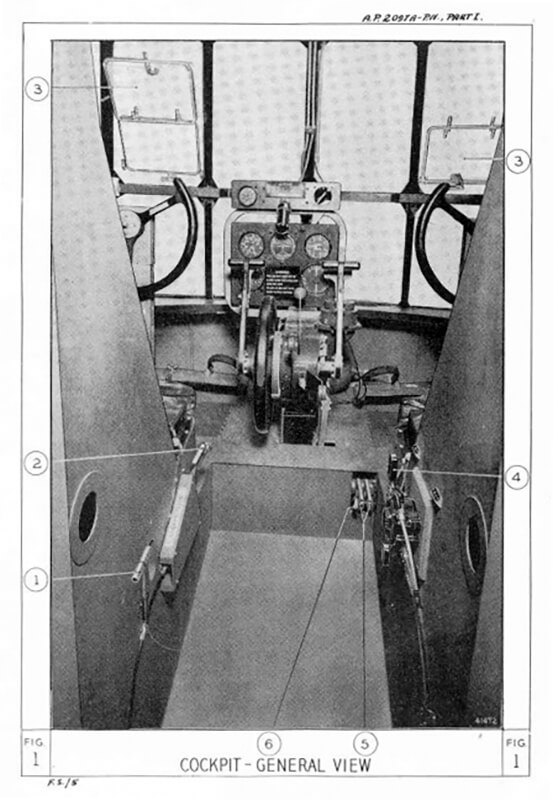
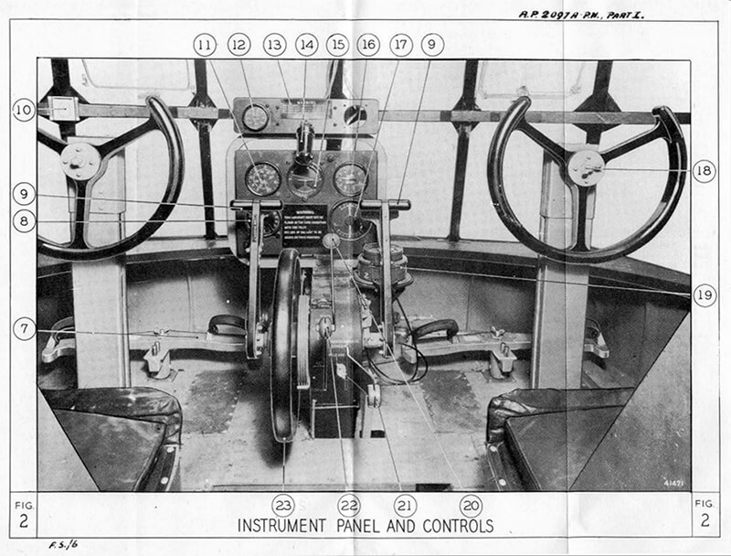
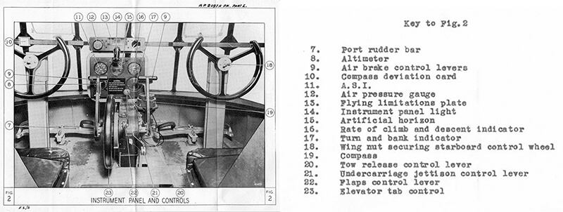
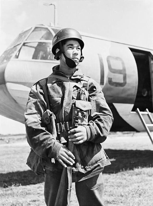
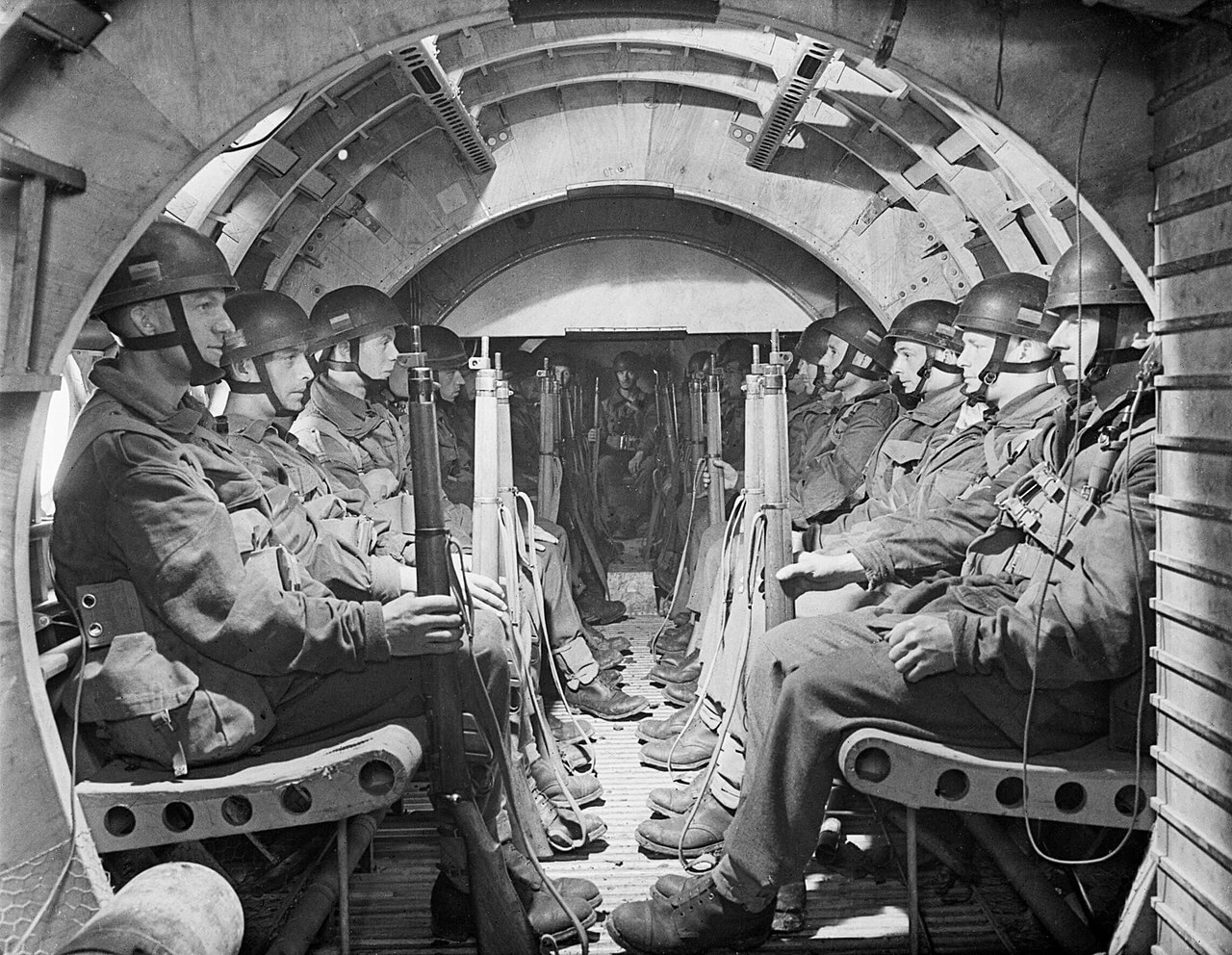
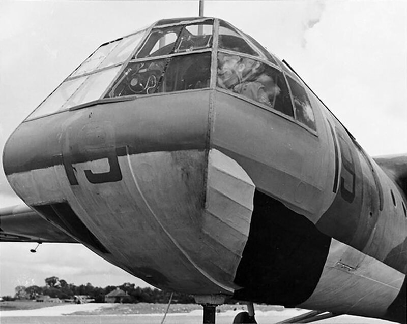
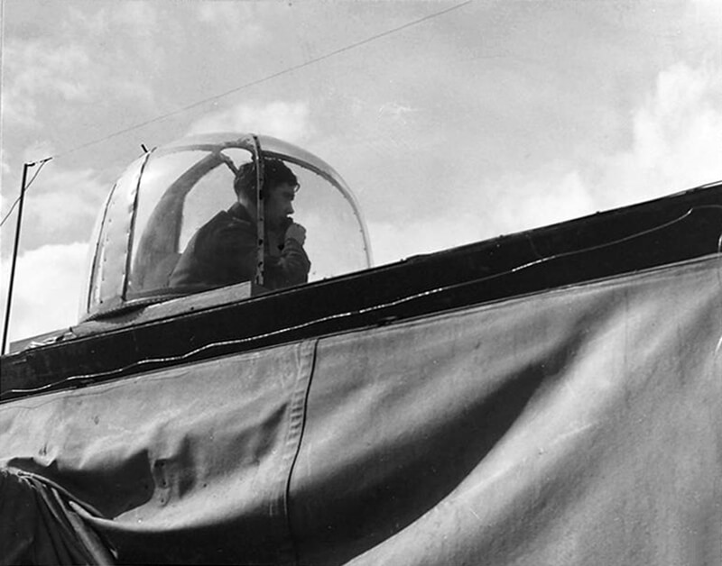
The Horsa, significantly larger than the Hotspur, is built to accommodate two pilots sitting side by side in a spacious cockpit covered by a Perspex canopy. The cockpit’s central pedestal contains various essential controls, including the compass, elevator trim-tab control, flap control, tow release, and undercarriage jettison lever. Initially, the brake lever is attached to the first pilot’s seat; however, in the Mark II version, it is moved to the control column. The instrument panel includes key flight instruments such as the air-pressure gauge, airspeed indicator, altimeter, and turn-and-bank indicator.
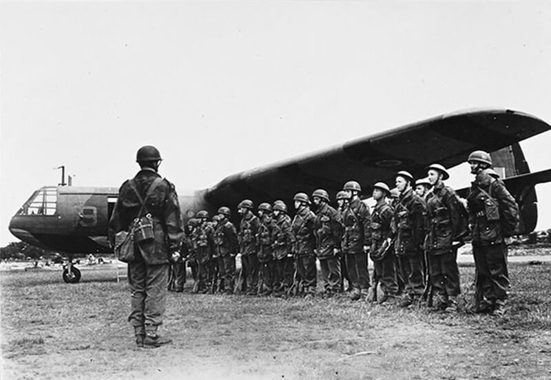
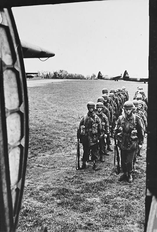
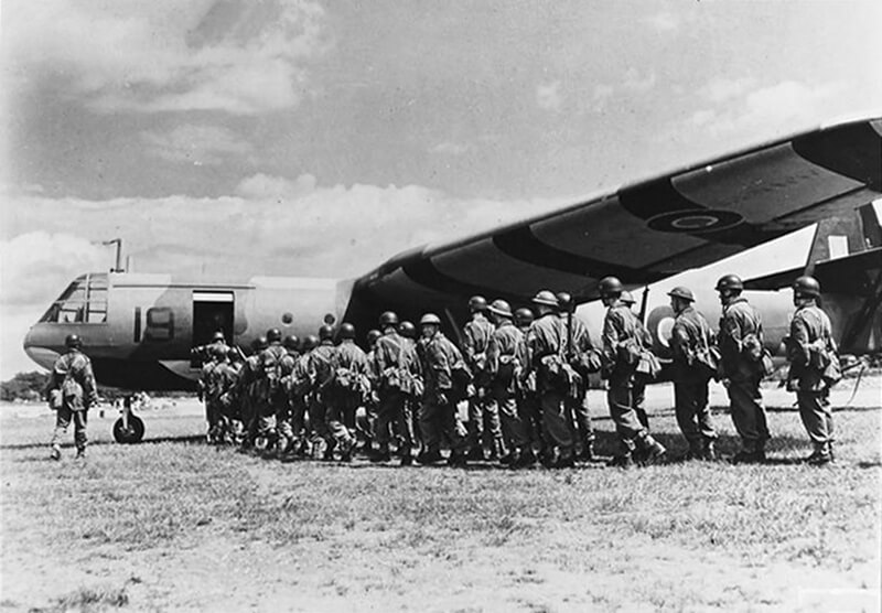
Originally, the Horsa is designed to transport troops in a concentrated formation, allowing them to be delivered on the ground as a cohesive fighting unit, unlike the dispersed nature of paratrooper drops. It also effectively doubles the number of paratroopers that a bomber can transport, being equipped with two widely separated passenger doors on either side of the fuselage, enabling simultaneous exits.
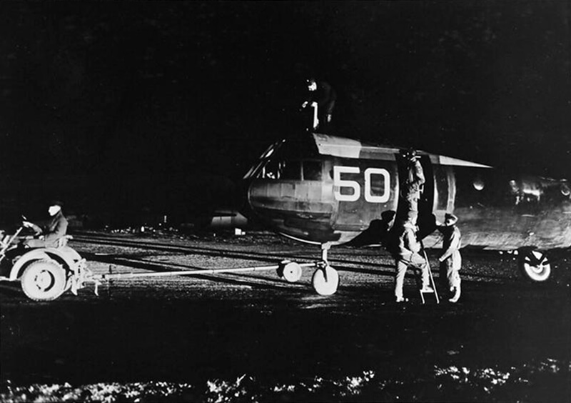
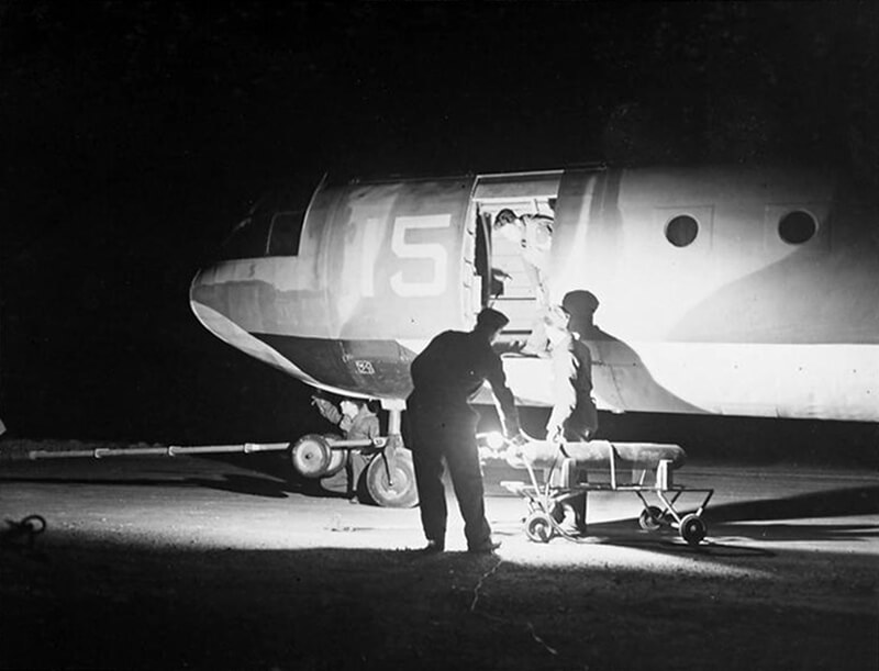
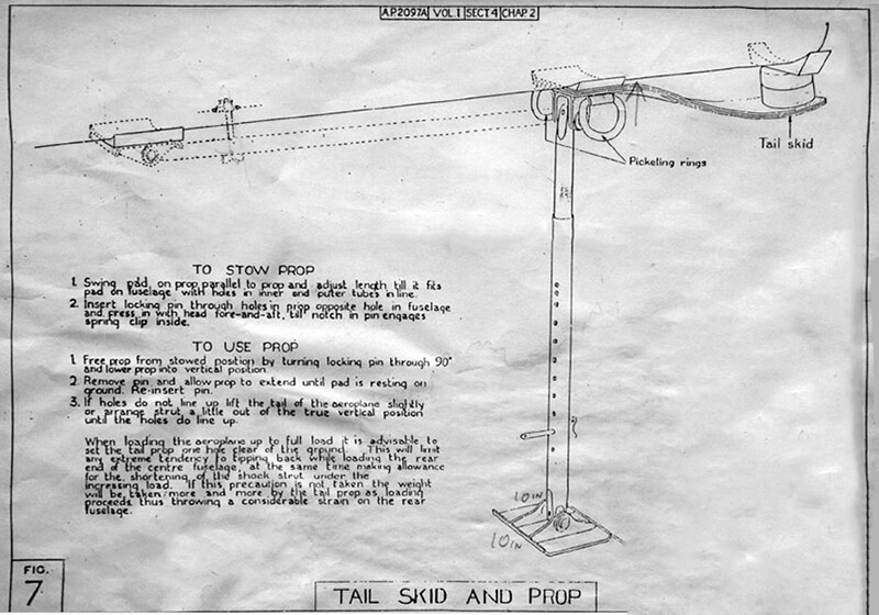
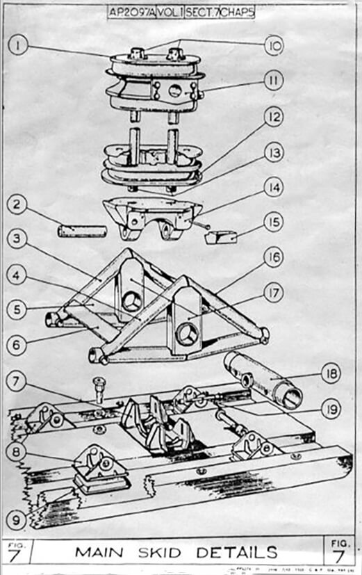
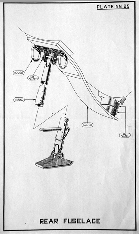
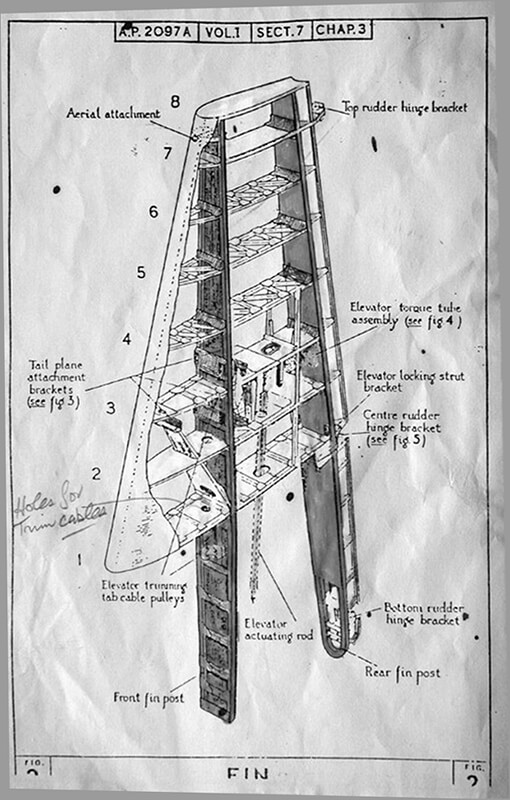
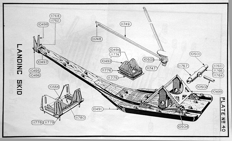
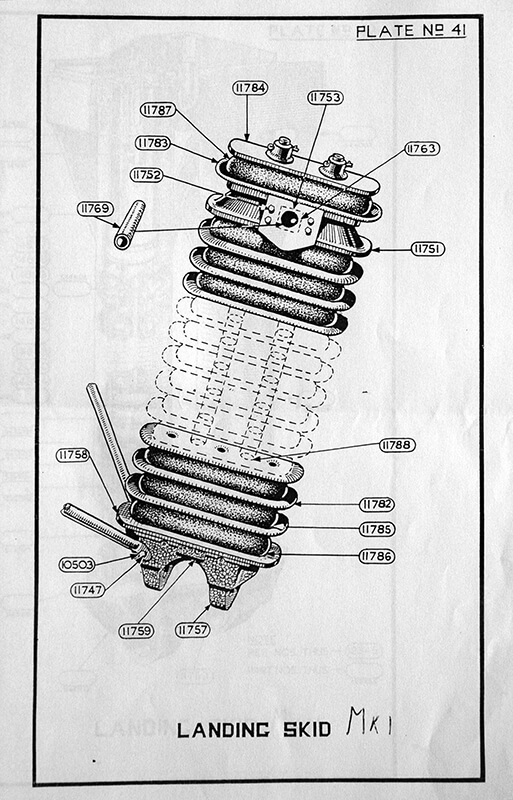
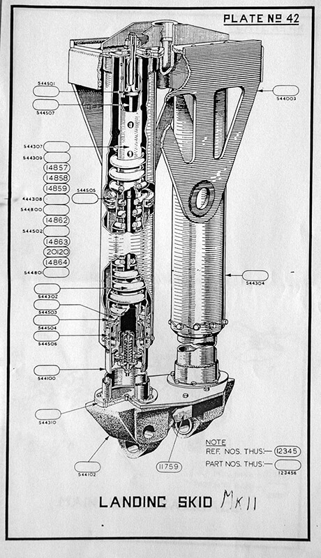
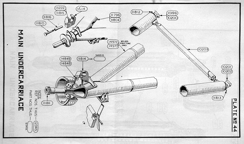
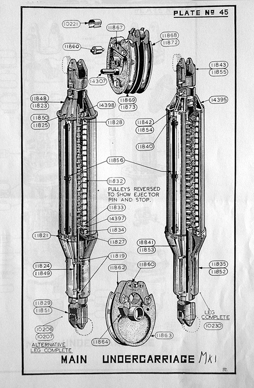
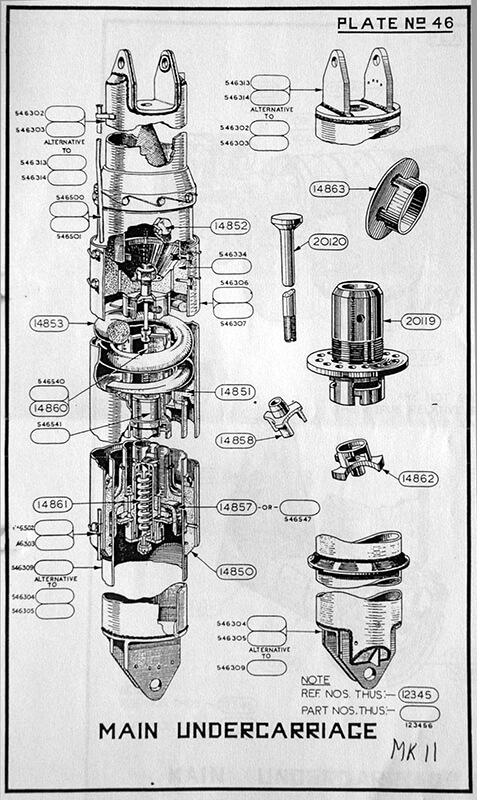
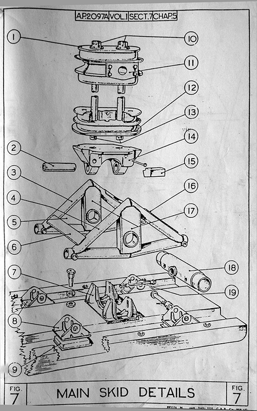
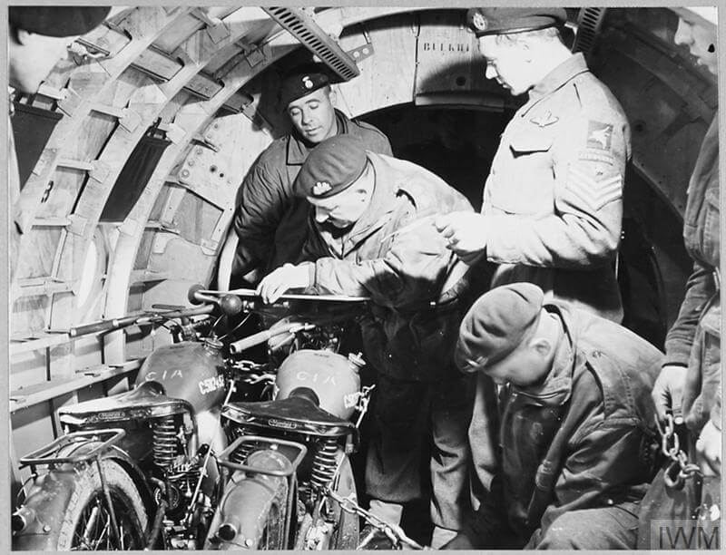
The Horsa’s tricycle undercarriage is originally designed to be jettisoned after take-off. There is a sprung skid under the fuselage intended for landings. The undercarriage is later adapted to carry heavier support weapons for airborne troops, it becomes standard to keep the undercarriage in place, providing better control after landing. The glider is initially intended to carry a solo or combination motorcycle as its only vehicle payload. To facilitate unloading of heavy equipment, a rectangular door is added on the port side of the fuselage, just behind the nose, hinged at the bottom to form an unloading ramp when lowered. To avoid damaging the ramp during loading, separate loading channels are used to bridge the gap between the ground and the glider’s floor.
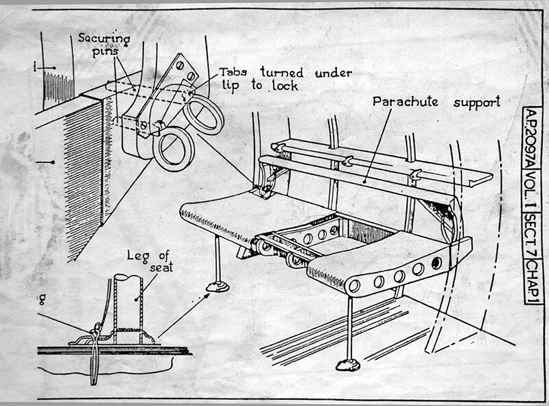
If the Horsa were ever used to drop paratroopers, they would secure their static lines to rails positioned above the doors as they prepare to jump, with supporting arms and supplies carried in containers stored within wing cells.
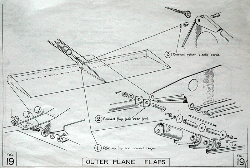
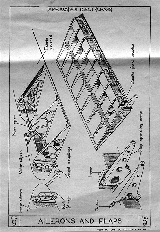
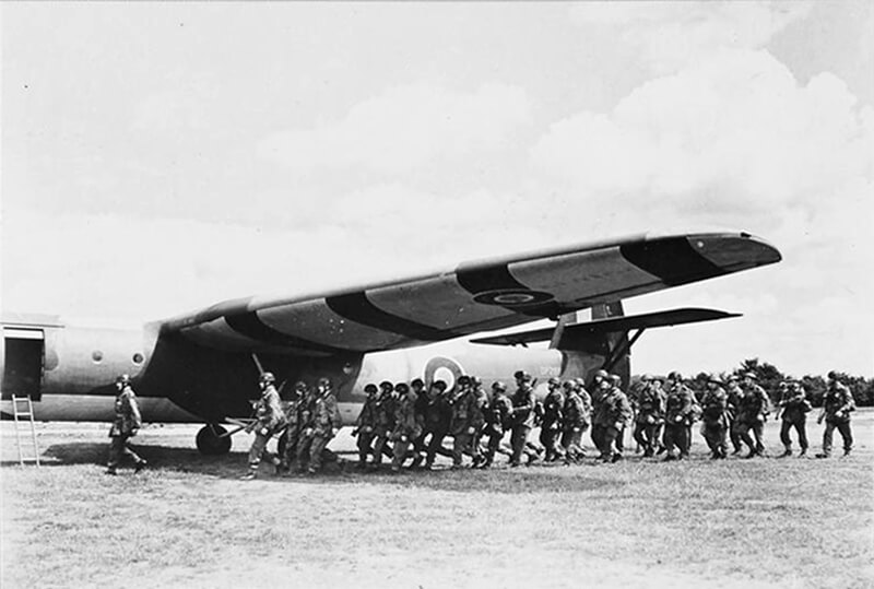
The wings have large “barn door” flaps allowing for steep, controlled descents into confined landing zones. The glider has dual controls and side-by-side seats for two pilots. A hinged cargo-loading door on the port side doubles as a ramp, and the main compartment can accommodate thirty soldiers on bench seats. Soldiers can also enter and exit through a smaller starboard side door. Rapid unloading is facilitated by breaking the fuselage joint at the rear of the main section. The design includes a feature where the doors can be opened in flight by sliding them upwards into the fuselage, making them suitable for use as Bren gun positions. Additional apertures are placed on the top of the fuselage at the centre of the wing and at the tail for the same purpose, though these gun positions are never used in practice.
The use of the Horsa glider evolves to include delivering heavy support weapons to assist airborne troops, rather than just transporting personnel, particularly when troops are out of range of friendly fighter cover or artillery support. The British 25-pounder gun, weighing nearly two tonnes, requires significant modification to fit inside a Horsa, but this is eventually achieved by designing a new Mk III carriage for it. However, the most widely carried artillery by the Horsa becomes the American 75 millimetre pack howitzer, which is adapted from pre-war animal transport use. Its compact design, folding trail, and ability to be broken down for parachuting make it ideal for glider deployment, able to be transported complete with its ammunition and a jeep for mobility.
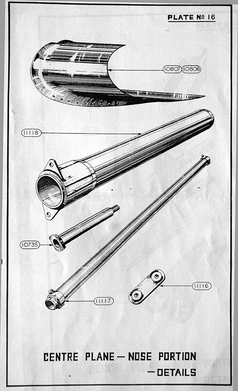
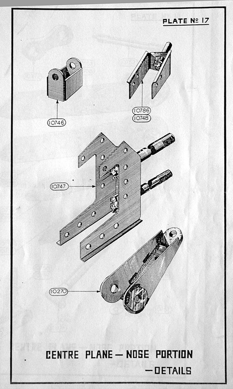
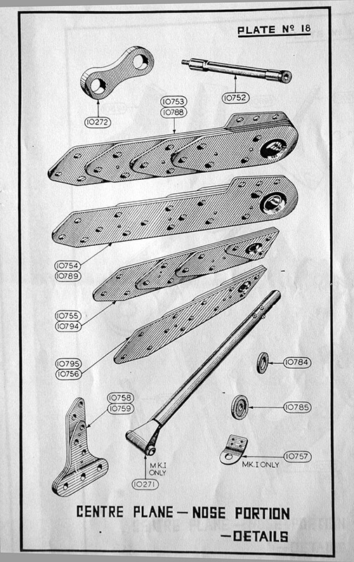
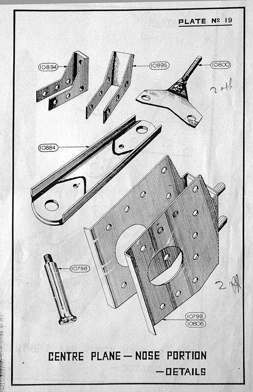
Soon, other potential loads, including arms and equipment weighing up to 3,175 kilograms, are added to the list, necessitating the fitting of a hinged ramp to facilitate easier loading and unloading. By the time the Mark II Horsa is developed, it features a hinged nose, eliminating the need for cumbersome 90-degree turns during unloading.
If the Horsa were ever used to drop paratroopers, they would secure their static lines to rails positioned above the doors as they prepare to jump, with supporting arms and supplies carried in 5 CLE containers stored within wing cells.
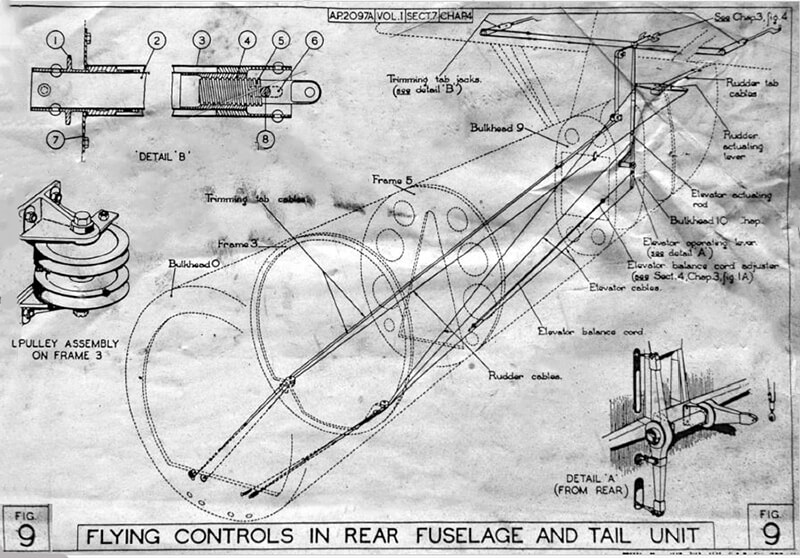
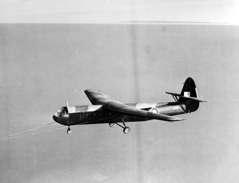
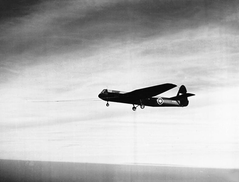
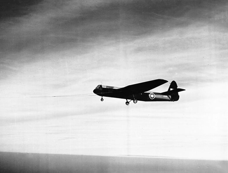
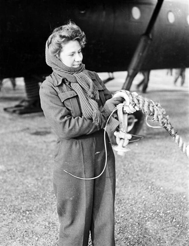
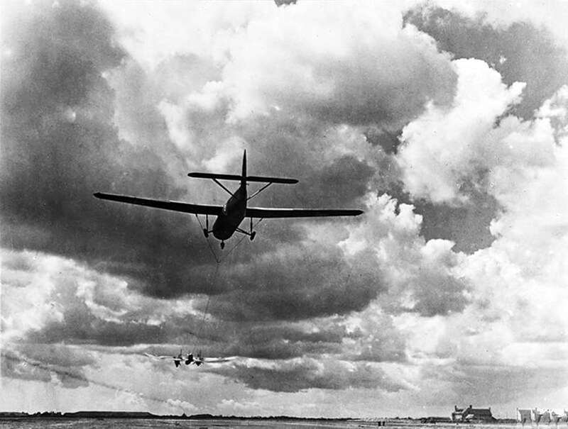
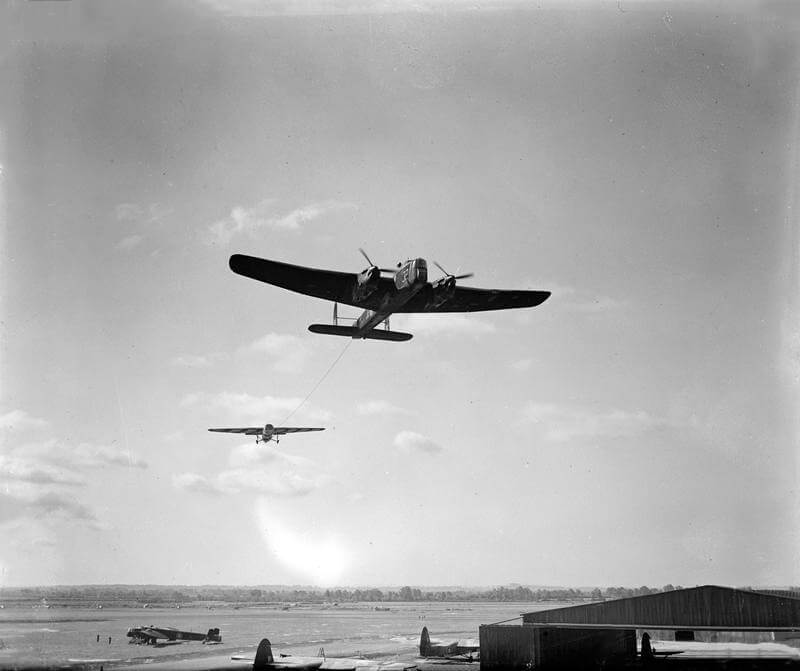
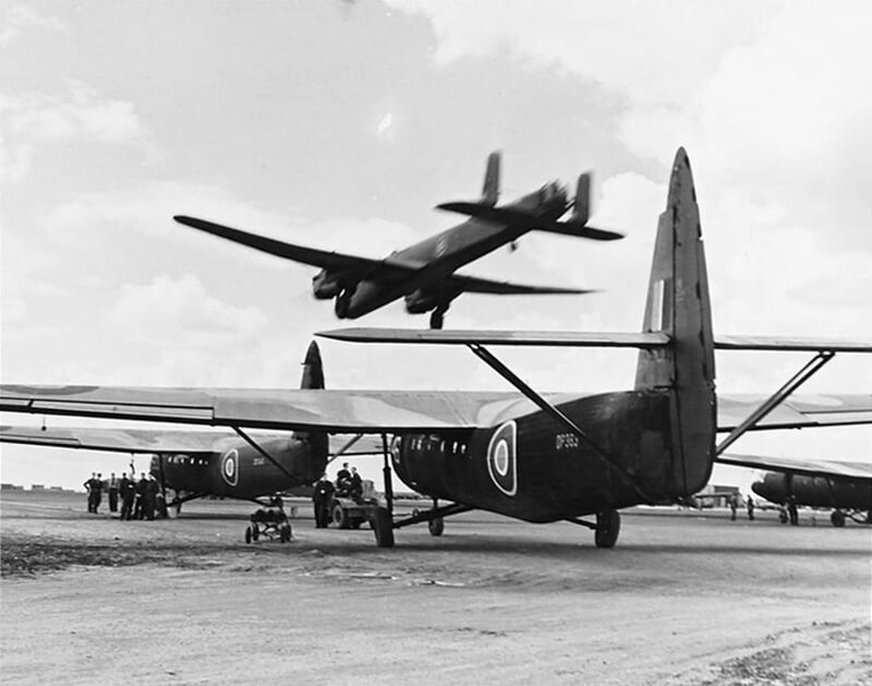
Both the glider and tug aircraft are equipped with tow-rope release mechanisms, allowing the tug to drop the rope after the glider pilot disengages. It is an established rule that the tug pilot should never release the glider from their end unless faced with an extreme emergency.
Communication between the glider and the tug is facilitated through a telephone cable woven into the tow rope, ensuring reliable coordination during flight.
| Versions |
AS.51 Airspeed Horsa I. Production glider with cable attachment points at upper attachment points of main landing gear.
AS.52 Airspeed Horsa. Bomb-carrying Horsa; project cancelled prior to design/production
AS.53 Airspeed Horsa. Further development of the Horsa not taken up.
AS.58 Airspeed Horsa II. Development of the Horsa I with hinged nose, to allow direct loading and unloading of equipment, reinforced floor, and double nose wheels for extra weight, with the tow attached to the nose-wheel strut instead of the wing points.
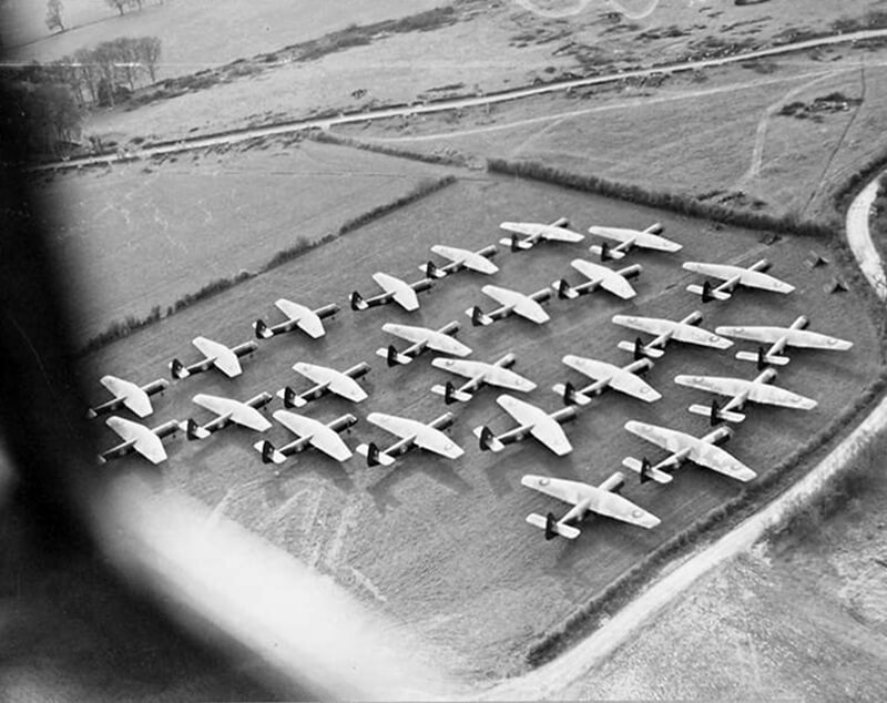
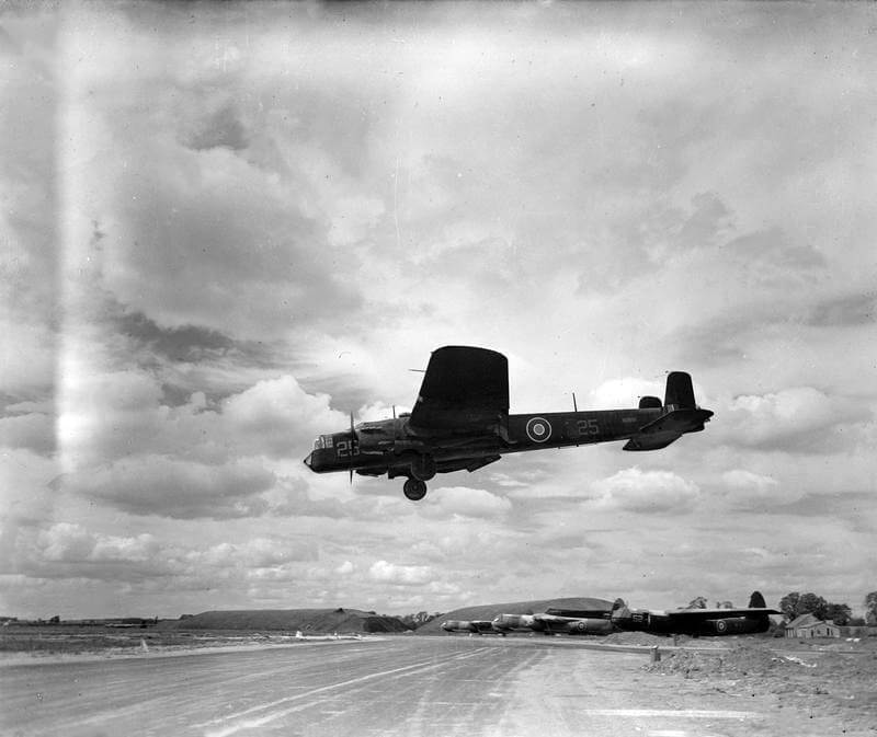
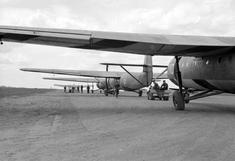
By the end of World War II, 3,655 Horsa’s have been built, with about 1,000 available for operations on D-Day.
| Loading the Horsa |
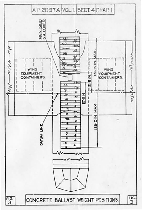
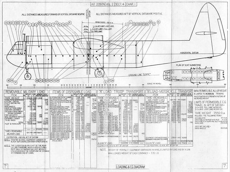
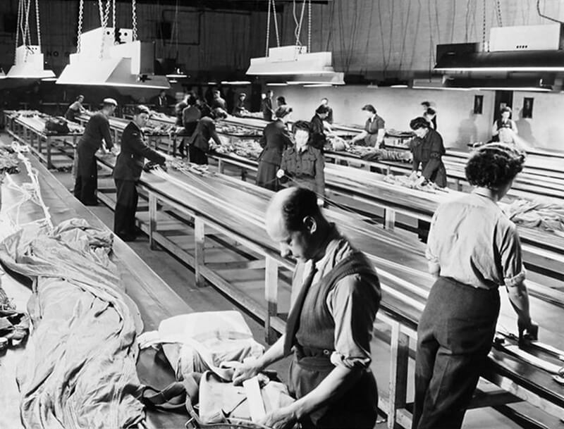
One of the critical pre-flight checks for glider pilots involves calculating the effect of the load on the glider’s centre of gravity (C of G) and its handling characteristics. An incorrect calculation can result in a crash. Glider pilots spend many hours learning how to perform these calculations and are equipped with a complex tool called the “CG and Weight Determinator,” which includes various weights to simulate different loads, alongside charts and tables to interpret the results. Despite this, few pilots fully grasp the complicated instrument, with many resorting to a more straightforward method: after loading, if the two pilots could swing on the tail section and lift the nose wheel slightly off the ground, the balance was deemed acceptable. Minor errors could then be adjusted using the trim control during flight.
| Operational Use and Lessons Learned |
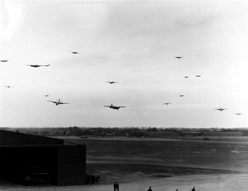
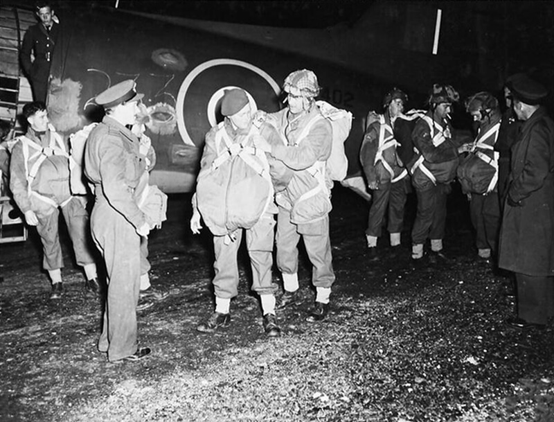
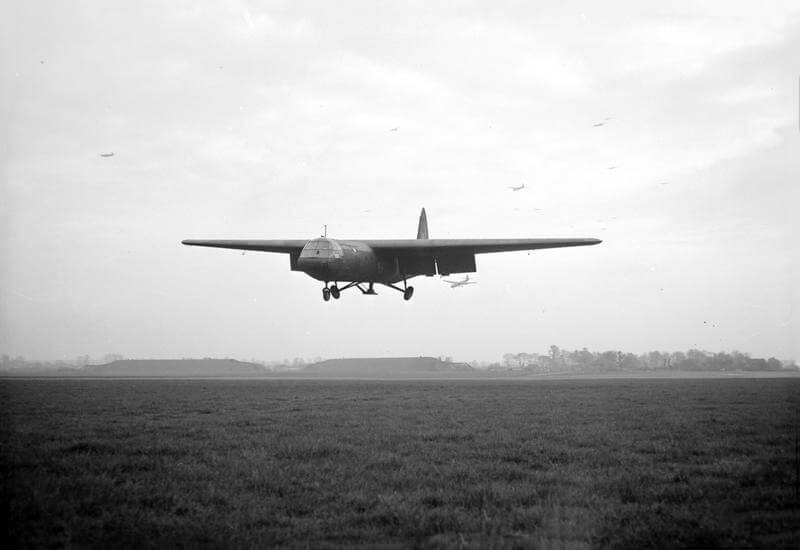
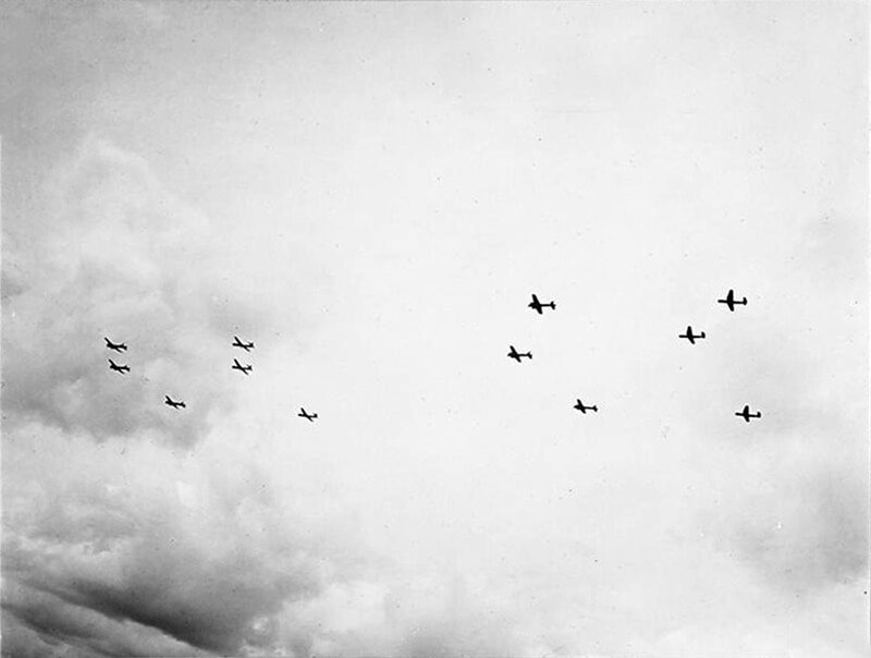
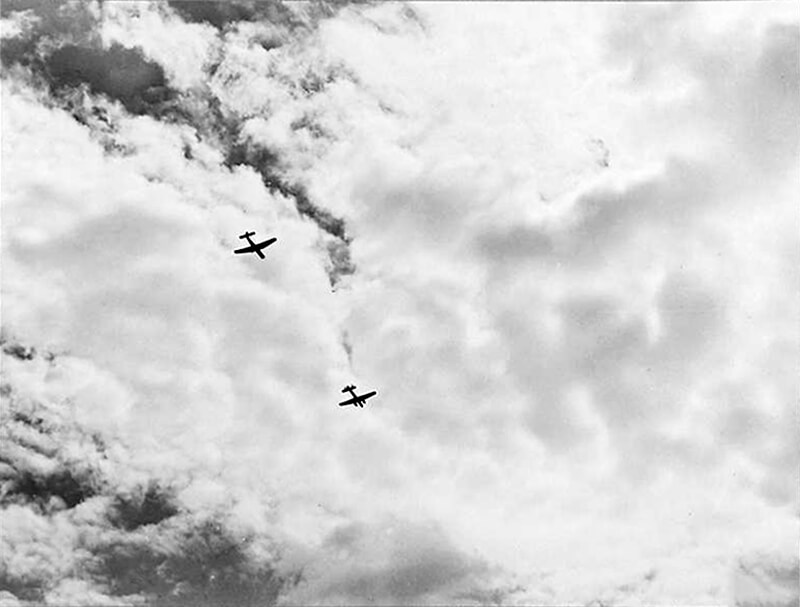
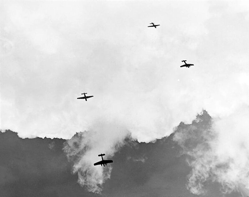
The Horsa’s operational debut is during the landings on Sicily in Operation Husky in July 1943. Pilots undertake a long and hazardous journey under tow from southern England to airfields in North Africa. The operation faces high casualties due to several factors, including some gliders being released too far from the coast and ditching at sea, and friendly fire from Allied anti-aircraft gunners mistaking them for enemy aircraft.
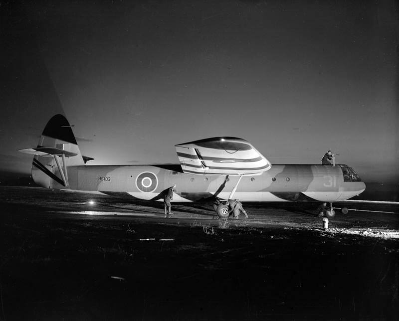
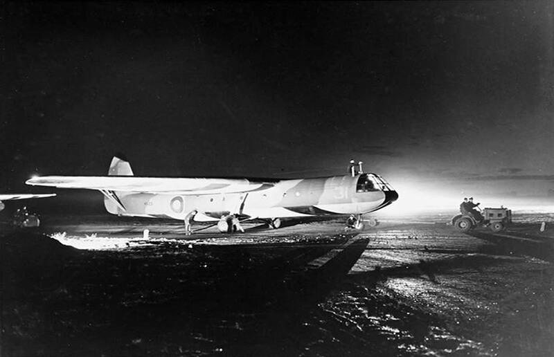
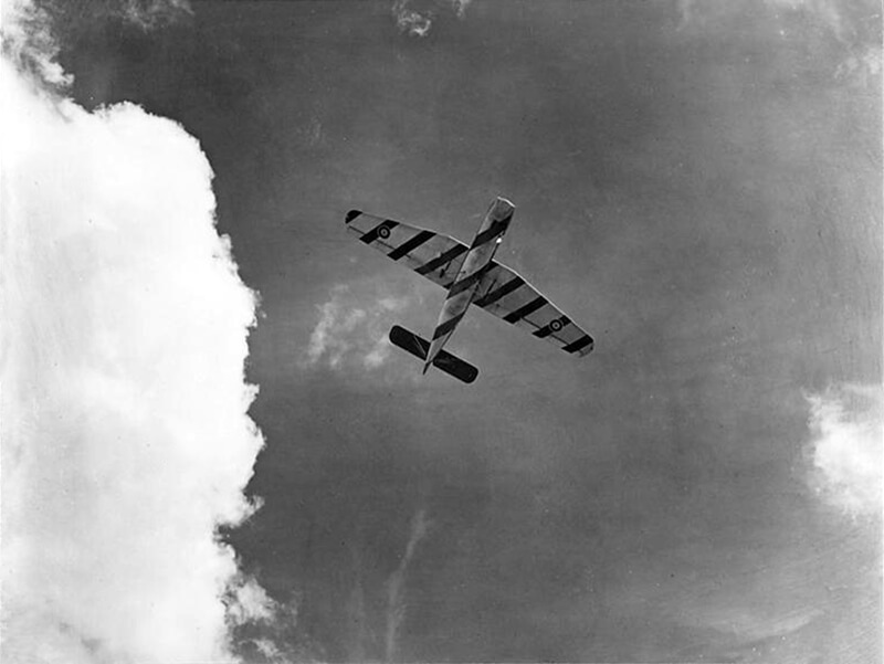
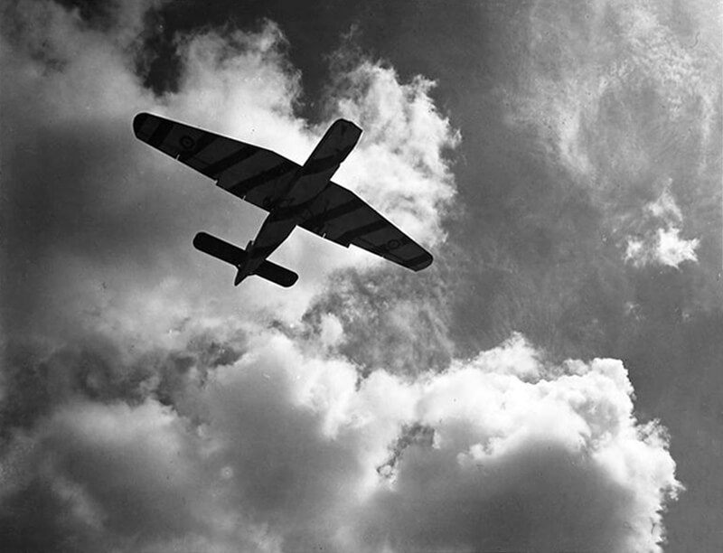
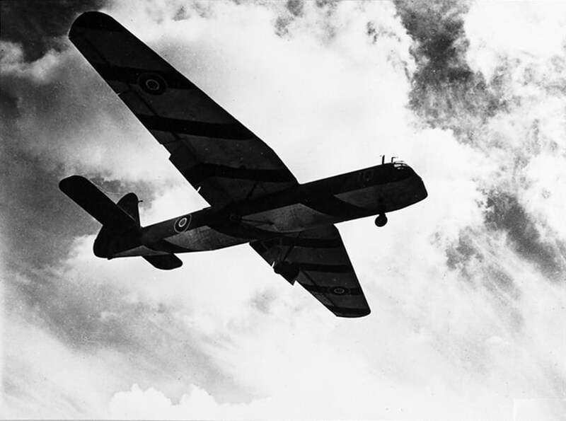
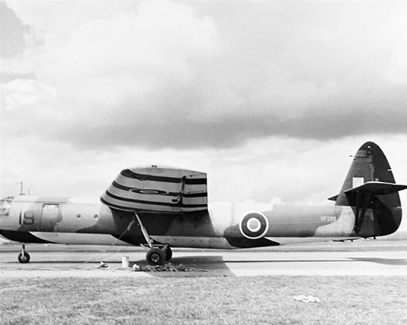
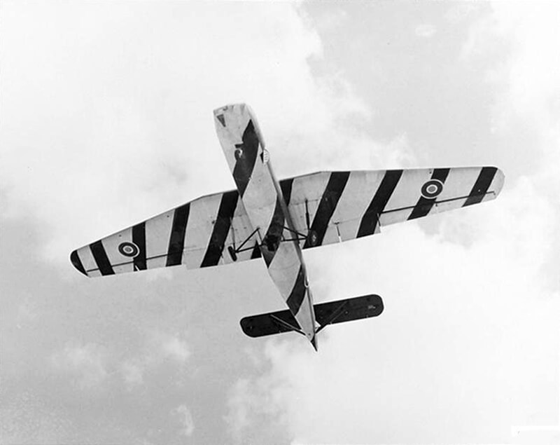
Lessons from Husky are applied by D-Day, with new drills to prevent similar tragedies. A dramatic measure involves painting bold black and white stripes on wings and fuselages, D-Day stripes. Allied anti-aircraft gunners are instructed not to engage any aircraft with these markings, ensuring safer operations for all Allied aircraft over Normandy.
For the six Horsa Gliders used during the Coup de Main to capture the bridges adaptions are made to perform their mission.
The three Horsa’s that would attack the Caen Canal bridge would require specific modifications. Because they are flying right-handed turns, the first pilot is advised to fly on the right-hand side of the glider, contrary to the usual left-side position. Under the perspex front of the cockpit, a second panel is cut and fitted with perspex, allowing an almost vertical view of the ground, and providing an extra window for better visibility.
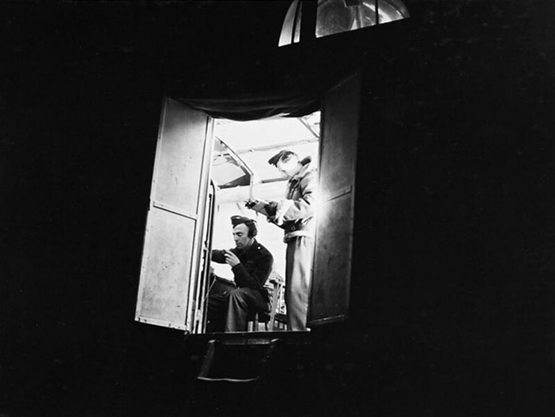
The command pilot occupies the right-hand seat to maintain a clear view of the bridge during a descent rate of 750 metres per minute at an angle of about forty-five degrees. This positioning allows for better right-hand circuit navigation. The co-pilot uses a small torch to avoid interfering with the pilot’s vision and manages a stopwatch. Additionally, a direction finder (gyro-compass) is installed in the aircraft because the standard compass is not effective at a forty-five degree angle.
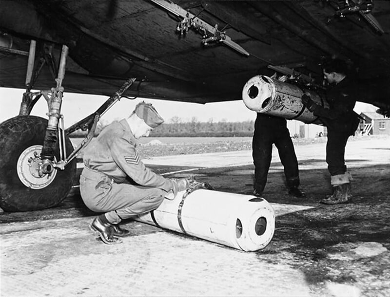
It is also recognised that bringing seven tons, the combined weight of three tons of troops and the three and a half-ton glider, down into a small field from 1,800 metres and bringing it to a stop is quite challenging. Although the glider excels in short landings using full flaps, there remains the problem of fitting three gliders, or even one, into that field with the landing run, especially with two more gliders following closely behind. Consequently, the decision is made to install drag chutes. This idea is proposed by Flight Lieutenant Grant, who observed the Americans using them during trials in the United States.
During the night of June 2nd, 1944, a team of Airspeed engineers, equipped with mobile workshops, arrives at Tarrant and begins modifying the six gliders. An arrester parachute is fitted into each tail. To unload the Mk 1 Horsa glider, there is a double bulkhead aft of the trailing edge of the main planes, featuring six quick-release bolts to drop the tail out of the way. This section includes a panel on the lower part of the fuselage that can be lowered to attach a rifle or other weapon for use upon landing.
The parachute, connected to the bulkhead, is placed in a box on this panel and can be operated from the cockpit using toggle switches in the centre of the instrument panel. One switch opens the trap door for the chute to fall out and deploy, while the other operates the release mechanism to discard the parachute. The Glider Pilots are concerned because, with the parachute lying on a loose panel on the floor, turbulence might cause the panel to be sucked out, leading to the parachute deploying while being towed across the Channel. Therefore, it is decided that the Oxf and Bucks or the engineer sitting in the rear seat of the glider will keep the parachute on their lap during the flight over the Channel. Once they have cast off, they will lean over the back of their seat and place the parachute onto the panel, positioning it for deployment.
| Multimedia |
| Movies |
| Photographs |
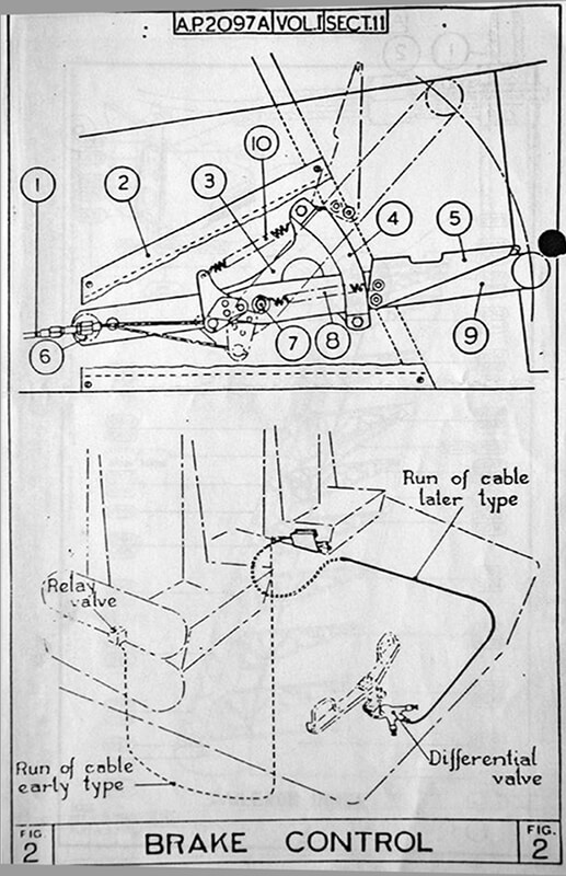
| Construction Plans |


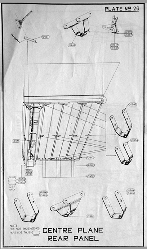
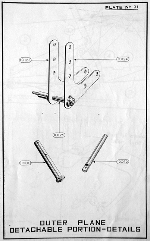
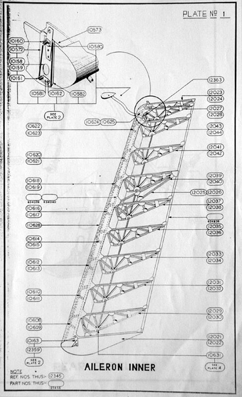
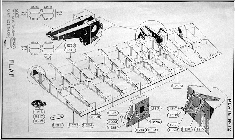
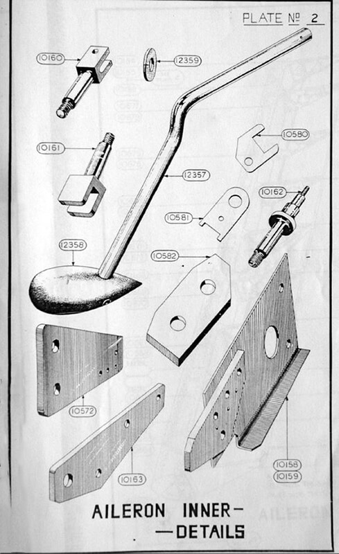
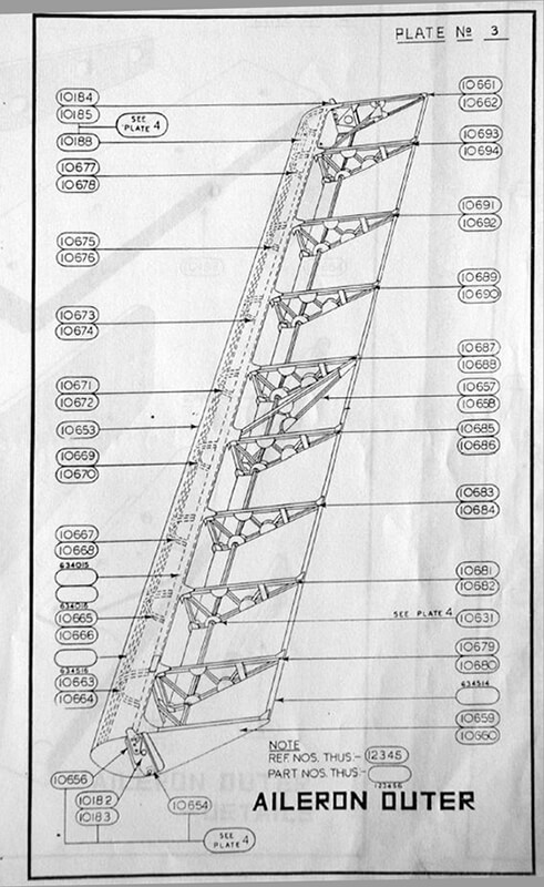
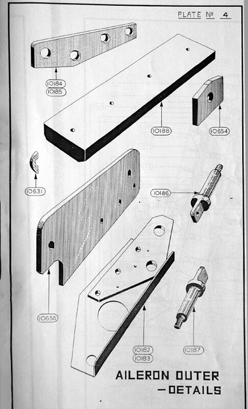
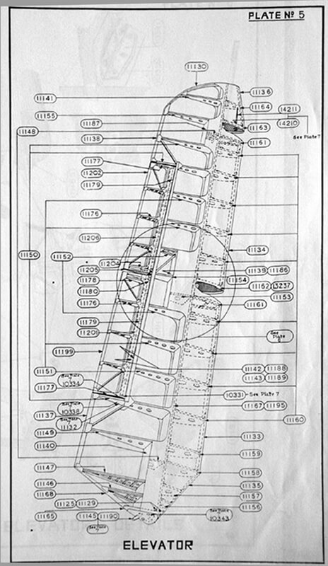
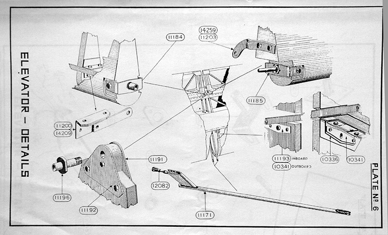
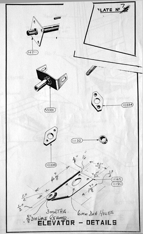
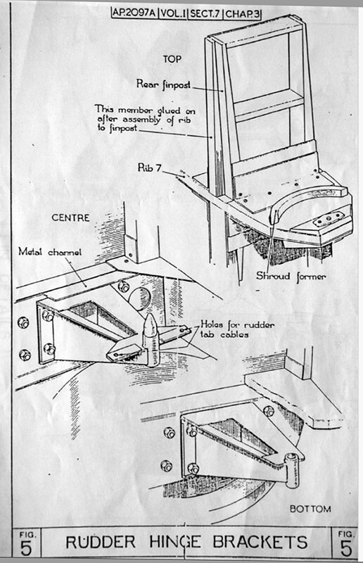
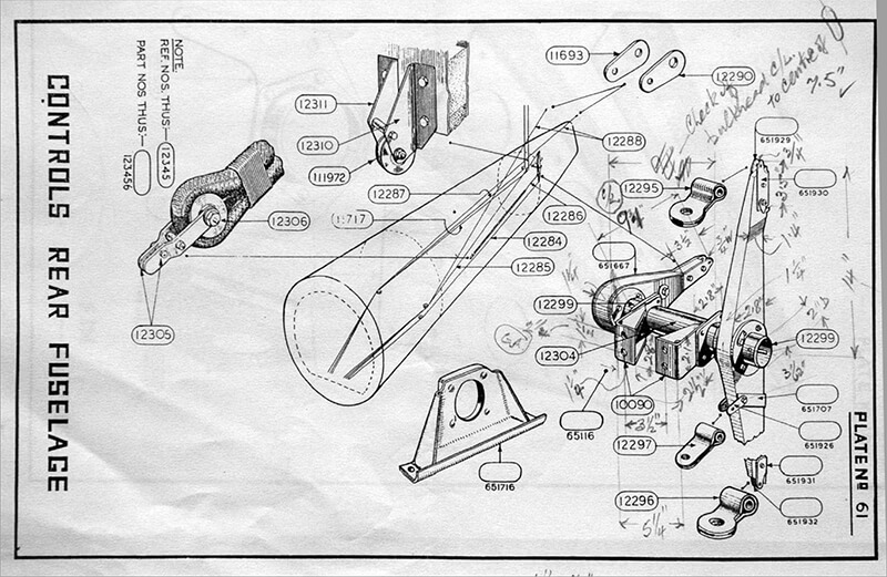
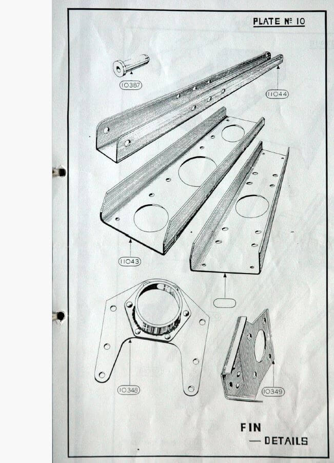
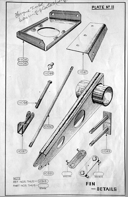
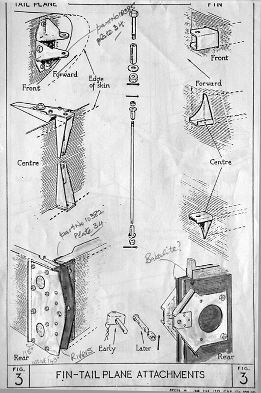
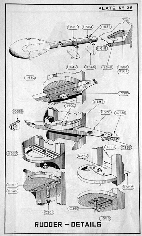
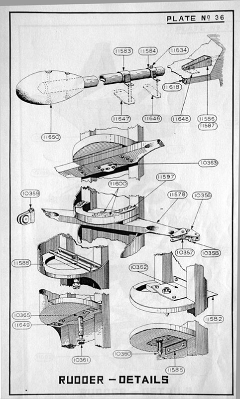
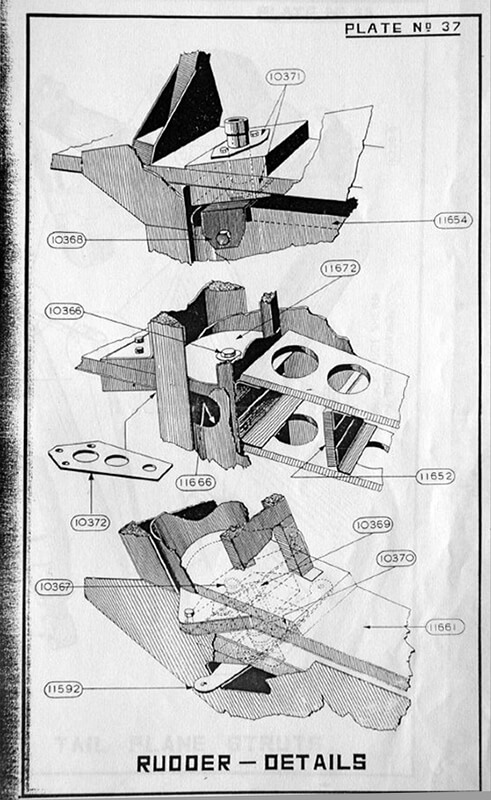
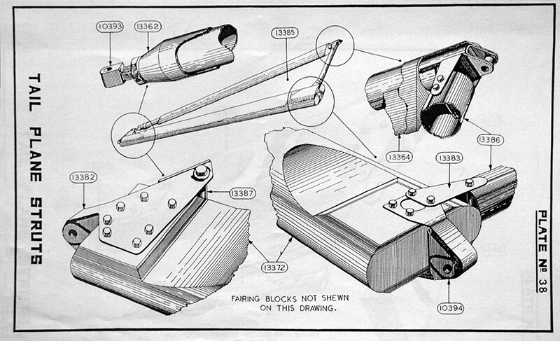


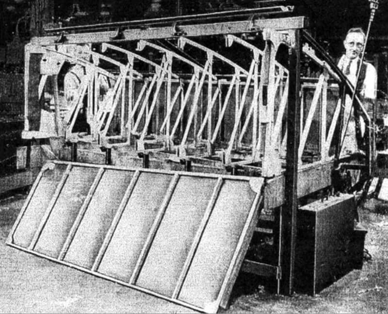
| Construction |
| Charts |


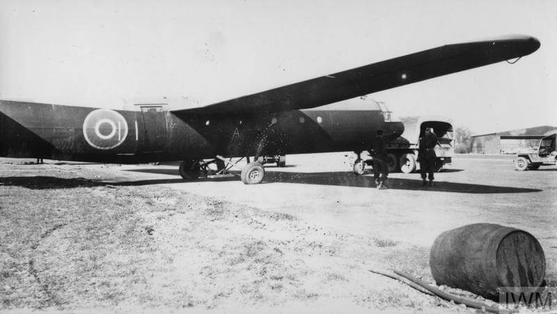
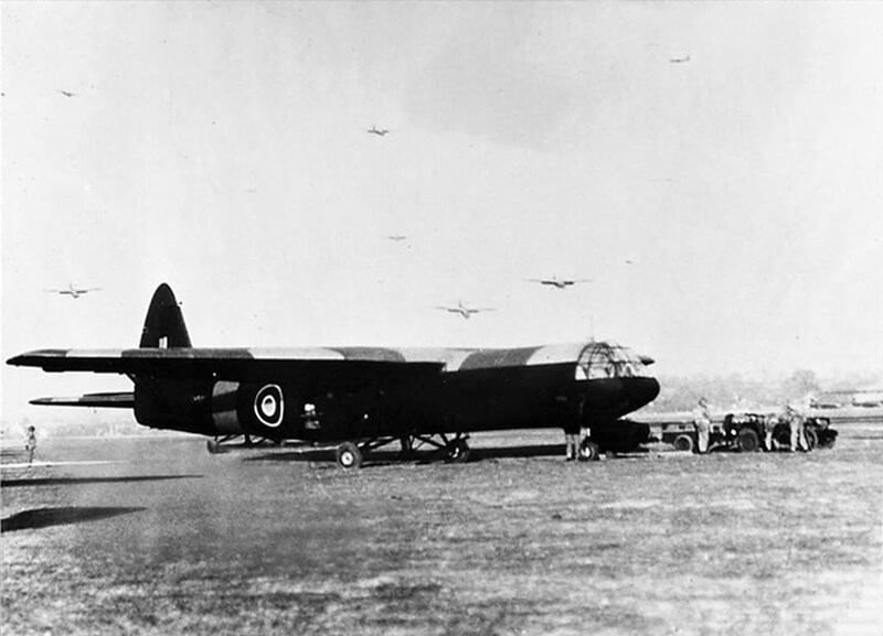
Handwritten caption on reverse: ‘RAF Horsa Glider.’ Copyright: © IWM. Original Source: http://www.iwm.org.uk/collections/item/object/205367991
![UNITED STATES NINTH AIR FORCE IN BRITAIN, 1942-1945 (FRE 3388) Horsa gliders of the 9th Air Force, Troop Carrier Command.
Not To Be Published 24 Apr 1944. On reverse: US Army General Section Press & Censorship Bureau [Stamps]. Copyright: © IWM. Original Source: http://www.iwm.org.uk/collections/item/object/205363427](https://worldwar2-sof.com/wp-content/uploads/2024/06/FRE_6413_1.jpg)
| Various |
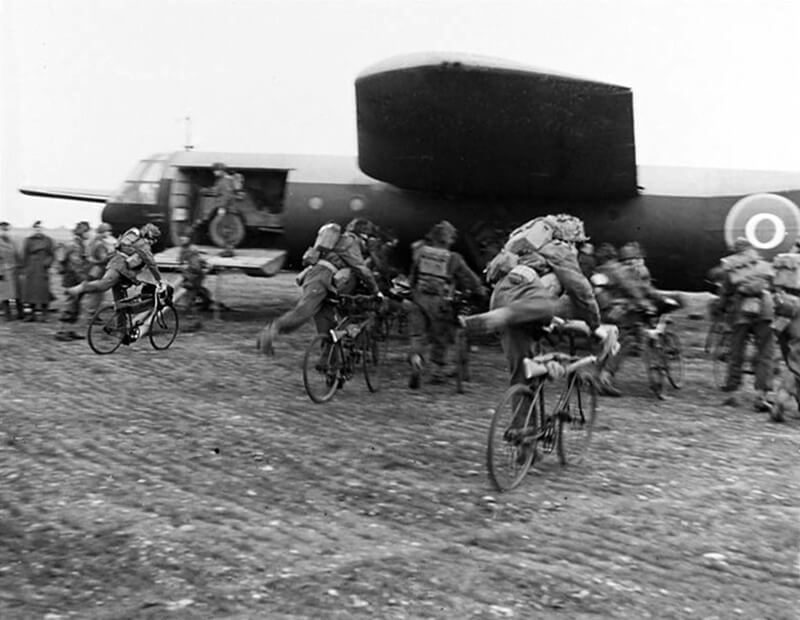
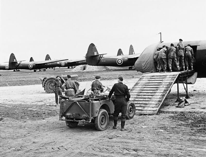
THE SKIES’ (CH 12830) Original wartime caption: CHIEF WATCHES AIRBORNE TROOPS ‘RAIN FROM THE SKIES’ For story see CH.12826. Picture (issued 1944) shows – Army cyclists ‘take off’ after landing from a Horsa glider. Copyright: © IWM. Original Source: http://www.iwm.org.uk/collections/item/object/205093069
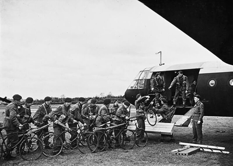
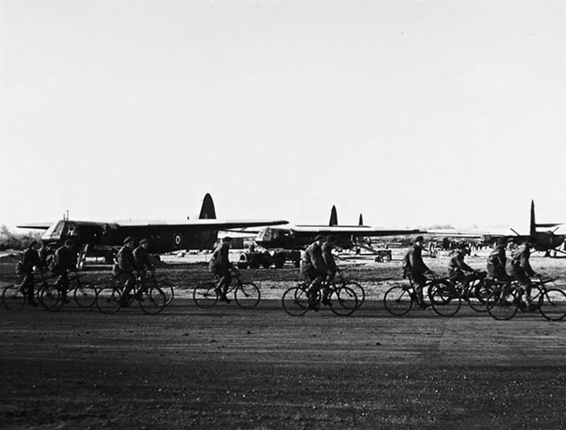
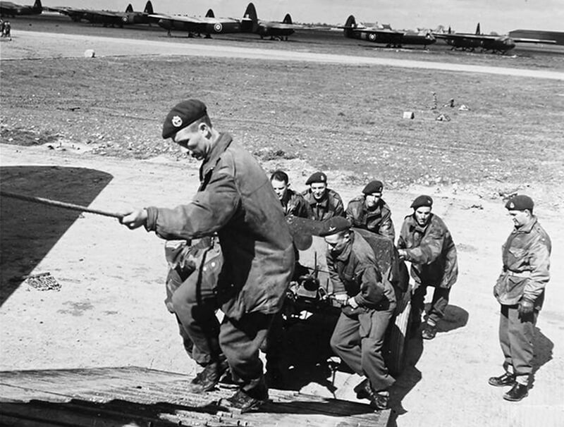
THE SKIES’ (CH 12828) Original wartime caption: For story see CH.12826. Picture (issued 1944) shows – Army cyclists going aboard a Horsa glider. Copyright: © IWM. Original Source: http://www.iwm.org.uk/collections/item/object/205093067
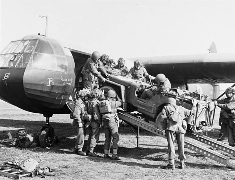
THE SKIES’ (CH 12834) Original wartime caption: For story see CH.12826. Picture (issued 1944) shows – Jeep being loaded into a Horsa glider. Copyright: © IWM. Original Source: http://www.iwm.org.uk/collections/item/object/205093071
THE SKIES’ (CH 12829) Original wartime caption: For story see CH.12826. Picture (issued 1944) shows – A Jeep being unloaded from a Horsa glider. Copyright: © IWM. Original Source: http://www.iwm.org.uk/collections/item/object/205093068
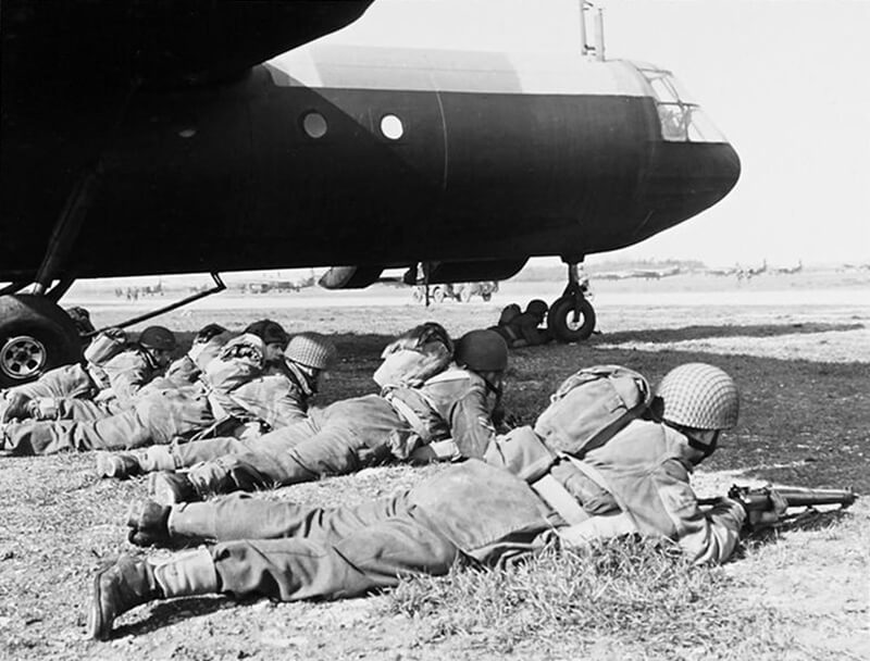
THE SKIES’ (CH 12831) Original wartime caption: For story see CH.12826. Picture (issued 1944) shows – Under the shadow of a Horsa’s wing, Army airborne troops mount guard whilst the glider is unloaded. Copyright: © IWM. Original Source: http://www.iwm.org.uk/collections/item/object/205093070
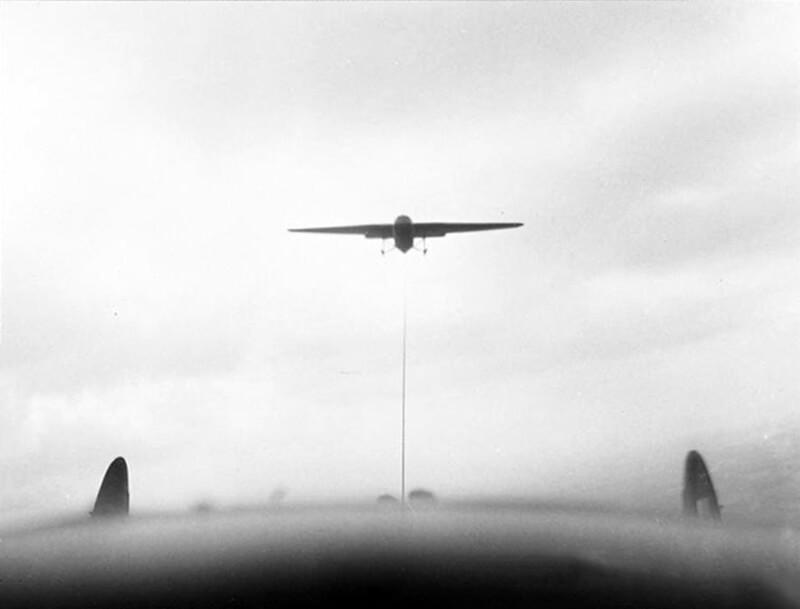
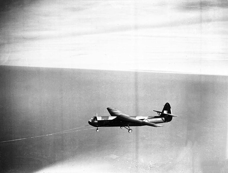
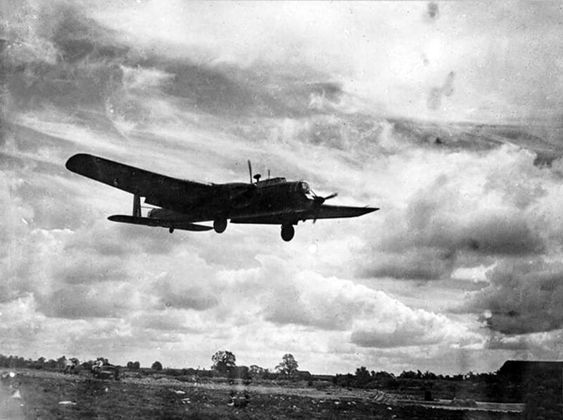
THE SKIES’ (CH 12838) Original wartime caption: For story see CH.12826. Picture (issued 1944) shows – A Horsa glider photographed from the tug aircraft. Copyright: © IWM. Original Source: http://www.iwm.org.uk/collections/item/object/205093075
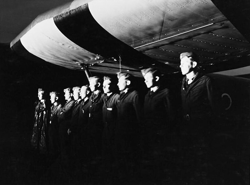
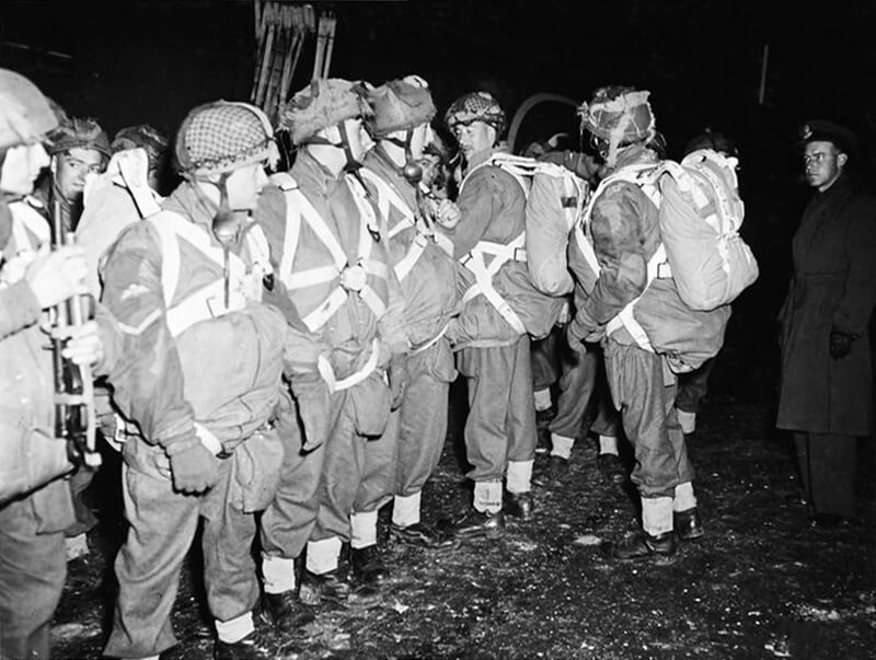
| Day Training |

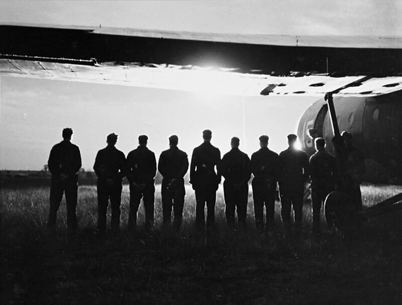
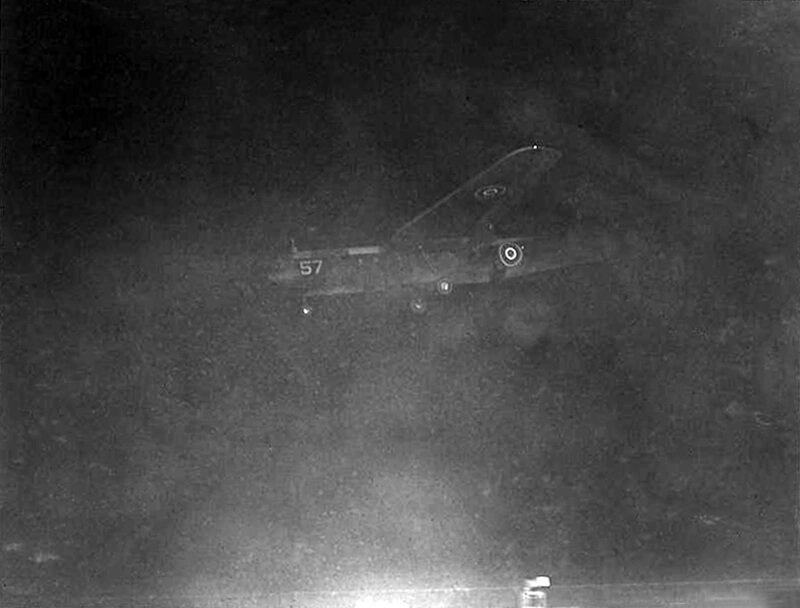
| Night Training |